Hydraulic drive engine air distributing mechanism

A valve train, engine technology, applied in the direction of engine components, machines/engines, non-mechanically actuated valves, etc., which can solve the inability to control the duration of the opening, it is difficult to achieve the best match of the engine, and the valves cannot be controlled at the same time. Problems such as the duration of the lift valve opening to achieve the effect of soft opening and closing

Active Publication Date: 2012-11-21
GREAT WALL MOTOR CO LTD
View PDF4 Cites 6 Cited by
  • Summary
  • Abstract
  • Description
  • Claims
  • Application Information

AI Technical Summary

Problems solved by technology

[0002] Improving the charging efficiency of the engine is an effective way to improve the economy and power of the vehicle. At present, the VVT ​​technology that has been used on the automobile engine is to adjust the phase of the intake and exhaust valves according to the different working conditions of the engine, that is, to adjust the intake and exhaust valves. The opening and closing timing of the valve, but it cannot control the valve lift and the duration of the valve opening at the same time, and cannot fully meet the intake requirements of the engine under this working condition
[0003] As we all know, the optimal air intake required by automobile engines under different working conditions is not the same. Since the profile of the cam in the traditional engine valve train is fixed, it is difficult to achieve the best matching with all the working conditions of the engine. Effect
Although the opening and closing timing of the intake and exhaust valves can be adjusted through VVT technology, it is powerless to control the valve lift and the duration of the opening. Wearing defect

Method used


Image

  • Hydraulic drive engine air distributing mechanism

Examples


Embodiment Construction

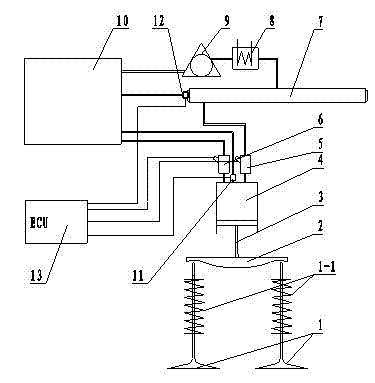
[0013] Referring to the drawings, the present invention includes a drive assembly, an actuator assembly, a hydraulic oil circuit, an oil storage tank 10 and a control system, the drive assembly is connected in the hydraulic oil circuit, and the hydraulic oil circuit is communicated with the oil storage tank 10, and the The actuator assembly includes a valve bridge 2, two valves 1 and a valve return spring 1-1. The upper end face of the valve bridge 2 is fitted with the drive assembly, and the lower end face is connected with the two valves 1. The valve return spring 1- 1 Set on the outside of the valve stem.

[0014] Referring to the drawings, the drive assembly of the present invention includes a high-pressure oil pump 9, a cooler 8, a high-pressure oil pipe 7 and a hydraulic cylinder 4. The inlet of the high-pressure oil pump 9 is connected to the oil storage tank 10, and the outlet of the high-pressure oil pump 9 is connected to the cooler 8. The cooling The outlet of the d...


PUM


Abstract

A hydraulic drive engine air distributing mechanism is used for improving the dynamic property, fuel economy and emission performance of vehicles, and includes a driving assembly, an actuating assembly, a hydraulic oil circuit, an oil storage tank and a control system, wherein the driving assembly is connected with the hydraulic oil circuit; the hydraulic oil circuit is communicated with the oil storage tank; the actuating assembly includes an air valve bridge, two air valves and an air valve return spring; the upper end face of the air valve bridge is assembled with the driving assembly, and the lower end face thereof is connected with the two air valves; and the air valve return spring is mounted outside an air valve stem in a sleeving manner. The engine air distributing mechanism realizes the fully variable air valve technology, can simultaneously control the opening / closing time, the opening continuity and the valve lift of the air valves, thereby being more suitable for the requirements of engine frequent variable working condition, reducing the engine oil consumption, ensuring the power output of the engine under high load, endowing the engine with the satisfactory idling characteristic, and providing technical support for the cylinder deactivation technology.

Description

technical field [0001] The invention relates to an engine air distribution mechanism controlled by an ECU and driven by a hydraulic oil cylinder, belonging to the technical field of engines. Background technique [0002] Improving the charging efficiency of the engine is an effective way to improve the economy and power of the vehicle. At present, the VVT ​​technology that has been used in automobile engines is to adjust the phase of the intake and exhaust valves according to the different working conditions of the engine, that is, to adjust the intake and exhaust valves. The timing of valve opening and closing, but it cannot control the valve lift and the duration of valve opening at the same time, and cannot fully meet the intake requirements of the engine under this working condition. [0003] As we all know, the optimal intake air volume required by the automobile engine under different working conditions is different. Since the profile of the cam in the traditional engi...

Claims


Application Information

Patent Timeline
Patent Type & Authority Applications(China)
IPC IPC(8): F01L9/02F01L9/10
Inventor 崔亚彬于文斌高定伟
Owner GREAT WALL MOTOR CO LTD
Why Eureka
Try Eureka