Clamping device for connection

A clamping device and fastening technology, applied in the direction of hose connection device, connecting member, friction clamping detachable fastener, etc., can solve the problems of product deviation, product quality obstacle, lack of availability, etc. Increased productivity, reliable quality management, and the effect of not complicating the overall structure

Active Publication Date: 2012-11-21
HONDA MOTOR CO LTD +3
View PDF8 Cites 11 Cited by
  • Summary
  • Abstract
  • Description
  • Claims
  • Application Information

AI Technical Summary

Problems solved by technology

[0009] In the clamping device for connection, it is necessary to manage the fastening force of the fastening belt from the viewpoint of quality maintenance, but none of Patent Documents 1 to 3 has a quality control means for keeping the fastening force constant. , in terms of the fastening force of the fastened part, the product is prone to deviation, which may become an obstacle to ensure product quality

Method used


Image

  • Clamping device for connection
  • Clamping device for connection
  • Clamping device for connection

Examples


Embodiment 1

[0090] [Structure of Embodiment 1]

[0091] based on Figure 1 to Figure 4 Embodiment 1 of the present invention will be described.

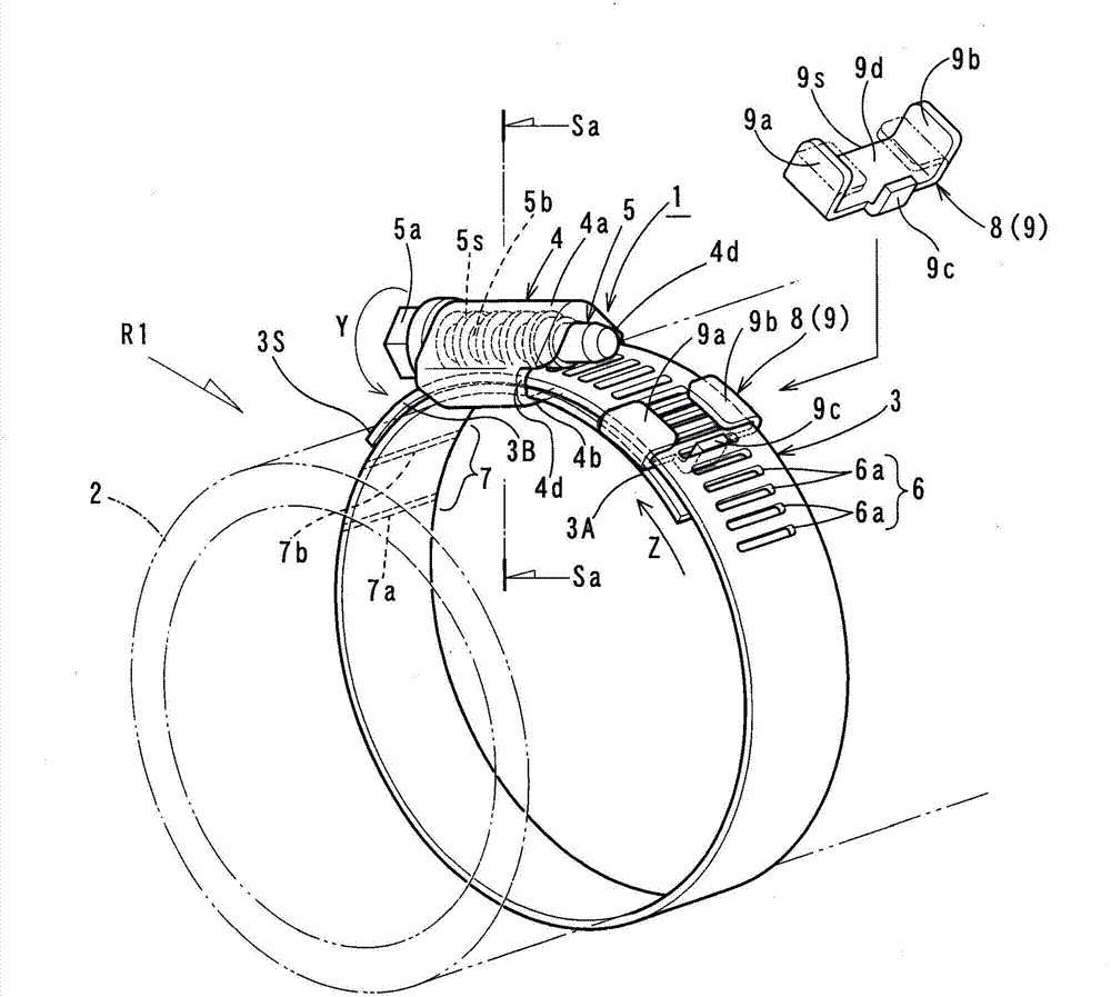
[0092] figure 1 The clamping device 1 for connection in is especially suitable for the case where the fastened part 2 such as a hose requires a large surface pressure fastening force, for example, for an engine with a supercharger (not shown), it is suitable for A case where an intercooler for cooling compressed air is connected to an intake pipe (both are not shown) to increase the filling rate of air. Hereinafter, the tightening force and the tightening force of the fastened portion 2 are used in the same meaning.

[0093] The clamping device 1 for connection includes an end-ring-shaped fastening belt 3 for fastening around the fastened portion 2 . The fastening band 3 is formed into a belt shape having a desired width and length, for example, from an elastic material such as a SUS304-based stainless steel plate.

[0094] For example, if ...

Embodiment 2

[0119] Figure 5 (a), Figure 5 (b) shows Example 2 of the present invention. The difference between Embodiment 2 and Embodiment 1 is that first notch grooves 9E are formed on both sides of the main body part 9d at one end part 9s of the blocking member 8, and second notches are formed at the bent parts 9a and 9b. Slot 9F (refer to Figure 5 (a)).

[0120] When the bent portions 9a, 9b of the rectangular plate 9 are crimped to the other end side 3B, the first notch groove 9E overlaps the second notch groove 9F, and the communication groove 9G is formed as a notch-shaped slit (see Figure 5 (b)). Then, when the tightening of the fastening tape 3 ends, as Figure 5 As shown by the dashed-dotted line in (b), the opening edge portion 4 d of the casing 4 meets and engages with the communication groove 9G as an engaged portion. In addition, the gap shape of the tooth portion 6a in the fastening belt 3 and the front end shape of the flange portion 9c may be set to be the same, ...

Embodiment 3

[0128] Figure 6 to Figure 8 Example 3 of the present invention is shown. Embodiment 3 differs from Embodiment 1 in that the stopper 8 is configured to also serve as the crushing member 13 .

[0129] Such as Image 6 As shown in (a), the rectangular plate 9 as the stopper 8 is formed with an oblong through-hole 9f from one bent portion 9a to the main body 9d, and an oblong through-hole 9g is formed from the other bent portion 9b to the main body 9d. .

[0130] The main part 9d of the rectangular plate 9 is formed with a small circular hole 9h as a hole and oblong holes 9j and 9k on both sides of the small circular hole 9h, and is hollowed out to reduce the size.

[0131] In the rectangular plate 9, one end portion 9s on the opposite side to the flange portion 9c also serves as a stopper portion 8A. In addition, in the rectangular plate 9, the arrangement area of ​​the through holes 9f, 9g, the small circular holes 9h, and the oblong holes 9j, 9k is defined as the plastic d...


PUM


Abstract

The invention provides a clamping device for connection. Through a stop member (8), the fastening force of a fastening belt (3) to a fastening part (2) can be maintained consistent. Through the rotation of a bolt (5), another end side (3B) of the fastening belt conducts relative sliding on the upper surface of one end side (3A), but the sliding amount of another end side (3B) is limited by the stop member (8). With the adoption of a fastening tool having fastening torque, a certain fastening force can be applied to the fastening belt (3). Accordingly, the fastening force of a fastening belt (3) to a fastening part (2) can be maintained consistent, high quality of a clamping device for connection (1) can be ensured, and production efficiency can be improved.

Description

technical field [0001] The present invention relates to a connection clamp for tightening with a constant fastening force by winding a fastening tape around these parts to be fastened when connecting a tubular member to a metal pipe, and causing the fastening tape to shrink in diameter and displace. device. Background technique [0002] In this connection clamping device, there are known hose clamps (for example, refer to Patent Document 1), worm wheel type hose clamps (for example, refer to Patent Document 2), or simple hose clamps, etc. (for example, refer to Patent Document 3 ). [0003] In Patent Document 1, a leaf spring as a biasing means is provided between an insertion cover that is bent so as to be crimped on the outer surface of the hose and the belt, thereby reducing the adhesion of the inner surface of the hose clamp to the outer surface of the hose. trend. Thereby, the hose clamp which does not generate|occur|produce leakage even after the expiration date, an...

Claims


Application Information

Patent Timeline
Patent Type & Authority Applications(China)
IPC IPC(8): F16L33/035F16L33/04F16B2/08
CPCF16L33/08
Inventor 矢沢加代子小见户拓铃木纯弥荒川纯一武田大中田裕明北浦启一栗野仁河合洁
Owner HONDA MOTOR CO LTD
Why Eureka
Try Eureka