Oil gasifier and oil burner

An oil burner, oil and gas technology, applied in the direction of burner, combustion method, combustion type, etc., can solve the problems of insufficient metal powder connection strength, blockage of oil gun nozzles, difficult quality, etc., to achieve compact structure, output will not be reduced, The effect of large heat capacity

Inactive Publication Date: 2012-11-21
YANTAI LONGYUAN POWER TECH
View PDF9 Cites 0 Cited by
  • Summary
  • Abstract
  • Description
  • Claims
  • Application Information

AI Technical Summary

Problems solved by technology

The porous gasification body sintered by powder metallurgy is difficult to control the quality of the metal powder material and particle size, so the si

Method used


Image

  • Oil gasifier and oil burner
  • Oil gasifier and oil burner
  • Oil gasifier and oil burner

Examples


Embodiment Construction

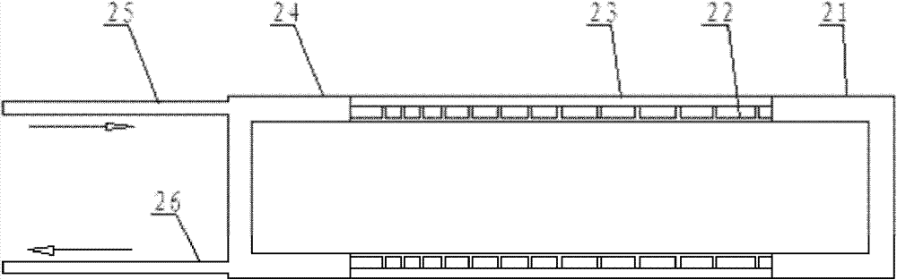
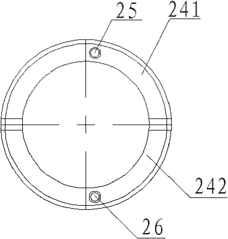
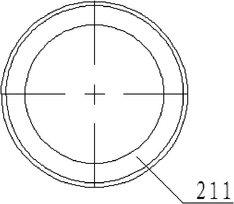
[0022] figure 1 The structure of an oil-gasifier according to an embodiment of the present invention is shown. Such as figure 1 As shown, the oil vaporizer includes a right end cover 21, a preferably hollow cylindrical inner sleeve 22, a preferably hollow cylindrical outer sleeve 23, a left end cover 24, an oil inlet joint 25, and an oil and gas output joint 26, wherein the outer sleeve 23 surrounds the inner sleeve 22. The right end cap 21 is airtightly arranged at one end of the inner sleeve 22 and the outer sleeve 23, and the left end cap 24 is airtightly arranged at the other end of the inner sleeve 22 and the outer sleeve 23, and between the right end cap 21 and the left end cap 24 and An annular space is formed between the inner sleeve 22 and the outer sleeve 23, and the annular space is provided with one or more continuous spiral grooves such as a rectangular cross section, and these spiral grooves will be formed by the left end cover 24 and the ends of the inner sleev...


PUM


Abstract

The invention relates to a multi-head spiral groove oil gasifier. The oil gasifier is characterized by comprising a first end cover (24), an inner sleeve (22), an outer sleeve (23), a second end cover (21), an oil inlet connector (25) and an oil gas output connector (26), wherein the outer sleeve encircles the inner sleeve, the first end cover is arranged at one ends of the inner sleeve and the outer sleeve in a gastight mode, the second end cover is arranged at the other ends of the inner sleeve and the outer sleeve in a gastight mode, annular space is formed between the first end cover (24) and the second end cover (21) and between the inner sleeve and the outer sleeve, one or more continuous spiral grooves are arranged in the annular space, and those spiral grooves enable the first end cover to be communicated with the second end cover so that fuel oil and oil gases can flow between the first end cover and the second end cover. The invention further relates to an oil burner with the oil gasifier. By means of the oil gasifier, the gasification efficiency is improved, the burning performance of the oil burner is obviously improved, and a large amount of diesel can be saved.

Description

technical field [0001] The invention relates to an oil vaporizer and an oil burner. Background technique [0002] At present, all kinds of oil burners at home and abroad are composed of oil guns, ignition guns, air distributors, burner stabilizers, flame detectors and other parts. The oil guns used in them, no matter how the specific structure changes, but their working principles use The fluid with high kinetic energy is ejected from small holes, and the oil is atomized by centrifugal force. Therefore, the oil mist particle size has become an extremely important technical index to measure the performance of the oil gun. The smaller the particle size of the oil mist, the higher the combustion efficiency, but it is difficult to achieve the particle size of the oil mist of the oil gun below 0.1mm. Therefore, the combustion efficiency of the oil gun is also limited to a certain extent. In order to further improve the combustion efficiency of the oil gun, people have come up ...

Claims


Application Information

Patent Timeline
IPC IPC(8): F23D11/44F23D11/00
Inventor 曹琴孙继国任志鹏李本伟蔡巍唐新新
Owner YANTAI LONGYUAN POWER TECH
Why Eureka
Try Eureka