Waveguide ring flange, flexible waveguide assembly containing waveguide ring flange and assembly method of flexible waveguide assembly

A flange and flexible waveguide technology, applied in waveguide-type devices, waveguides, electrical components, etc., can solve the problem of high-power microwave energy transmission and heat dissipation, and achieve simple and convenient assembly and disassembly, easy operation, and continuous guarantee. sexual effect

Active Publication Date: 2012-11-21
上海阖煦微波技术有限公司
View PDF7 Cites 5 Cited by
  • Summary
  • Abstract
  • Description
  • Claims
  • Application Information

AI Technical Summary

Problems solved by technology

[0005] In view of the fact that the existing flexible waveguide components are mostly cooled by peripheral cooling equipment, which cannot solve the problem of heat dissipation in the process of high-power microwave energy transmission, the purpose of the present invention is to provide a water-cooled waveguide flange with high heat dissipation efficiency, including the method Flexible waveguide assembly of blue plate and its assembly method

Method used


Image

  • Waveguide ring flange, flexible waveguide assembly containing waveguide ring flange and assembly method of flexible waveguide assembly
  • Waveguide ring flange, flexible waveguide assembly containing waveguide ring flange and assembly method of flexible waveguide assembly
  • Waveguide ring flange, flexible waveguide assembly containing waveguide ring flange and assembly method of flexible waveguide assembly

Examples


Embodiment 1

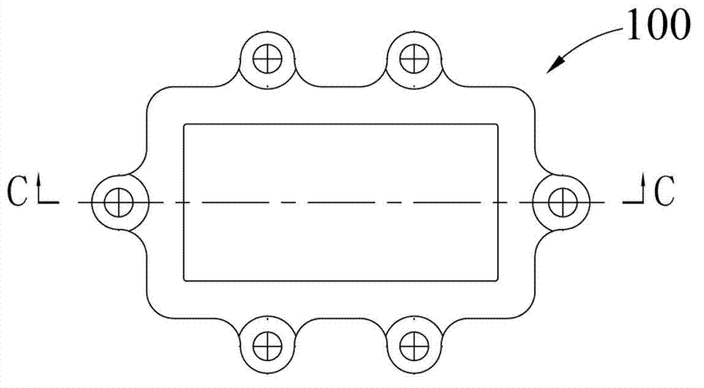
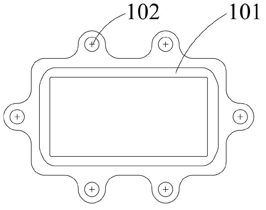
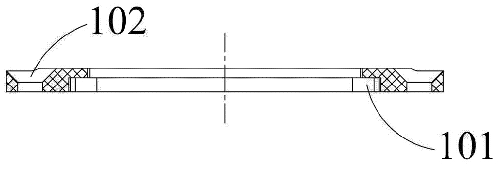
[0046] Example 1: Combining Figure 1 to Figure 6 The waveguide flange of the present invention is described, which consists of a first flange 100 and a second flange 200 . Such as figure 1 and image 3 As shown, the first flange 100 is a rectangular waveguide flange, the inner wall of which is closed and stepped and has a connecting surface 101 for connecting the waveguide, and the outer edge of the first flange 100 is evenly distributed with six installation Hole 102.

[0047] Such as Figure 4 to Figure 7 As shown, the second flange 200 is composed of a waveguide fixing part 201 and an outer sheath fixing part 202 which are integrated and communicated with each other. The outer diameter of the waveguide fixing part 201 is smaller than the inner diameter of the outer sheath fixing part 202 . The upper end surface of the waveguide fixing part 201 has a groove 205 matched with the first flange 100, and two water injection ports 203 are symmetrically arranged on the side wa...

Embodiment 2

[0049] Embodiment 2: The flexible waveguide assembly of the present invention is a transmission device used to supply energy to a tokamak. During high-power microwave transmission, a large amount of heat will be generated in the transmission medium due to transmission loss, so a cooling device is required to cool it To ensure the security of the transmission system. combine Figure 8 The flexible waveguide assembly 1 of the present invention is illustrated, which includes a waveguide 30, an outer sheath 40, a waveguide flange one 10 and a waveguide flange two 20, and the two ends of the waveguide 30 respectively pass through the waveguide flange one 10 and the waveguide flange two. The inner cavity of the waveguide flange 2 20 is welded on the two first flanges (11, 21), and the first flanges (11, 21) are respectively installed on the corresponding second flanges (13, 23 ) in the groove of the connecting hole and threaded on the second flange (13, 23). The outer sheath 40 is...

Embodiment 3

[0053] Example Three: Combining Figure 9 The flexible waveguide assembly 2 of the present invention is different from the second embodiment in that the waveguide flange 3 50 in this embodiment has a water injection port 3 52, the waveguide flange 4 60 has a water injection port 4 62, and the waveguide flange 4 60 has a water injection port 4 62. Both ends of the pipe 30 are respectively welded on the first flange (51, 61). The cooling water channel in this embodiment has only one water injection port and a water outlet, and its cooling efficiency is not as good as that of the double water injection ports in Embodiment 2, so it can be used in flexible waveguide components with lower power.


PUM


Abstract

A waveguide ring flange, a flexible waveguide assembly containing the waveguide ring flange and an assembly method of the flexible waveguide assembly relate to the technical field of waveguide transmission lines and aim at solving the problem that the heat radiation cannot be realized by a traditional flexible waveguide assembly due to the adoption of external cooling equipment. The waveguide ring flange comprises a first ring flange and a second ring flange, wherein a waveguide tube connecting surface is arranged on the inner wall of the first ring flange; the second ring flange consists of a waveguide tube fixing part and an outer jacket which are integrated and communicated with each other; the waveguide tube fixing part is provided with a groove matched with the first ring flange; and water injecting ports of which the output ends are communicated with an inner cavity of the fixing part are formed in the side wall of the fixing part. The flexible waveguide assembly comprises a waveguide tube, the outer jacket and two waveguide ring flanges; two ends of the waveguide tube are respectively connected to the ring flanges; two ends of the outer jacket are respectively connected to the two ring flanges; and the waveguide tube, the outer jacket and two water injecting ports form a cooling water channel. The assembly method comprises the steps of material falling, shaping, waveguide tube welding and outer jacket cold pressing. The waveguide ring flange, the flexible waveguide assembly containing the waveguide ring flange and the assembly method of the flexible waveguide tube assembly, disclosed by the invention, are mainly used in the fields of communication, satellite ground stations, microwave measurement and the like.

Description

technical field [0001] The invention relates to the technical field of waveguide transmission lines, in particular to a waveguide flange for connecting microwave equipment, a water-cooled flexible waveguide assembly containing the flange, and an assembly method for the assembly. Background technique [0002] At present, there are many kinds of transmission media used in the process of high-power energy transmission, and there are many forms of transmitted energy. Among them, transmitting energy in the form of microwave is a new type of wireless energy transmission technology. During high-power microwave transmission, a large amount of heat will be generated in the transmission medium due to transmission loss. If the heat dissipation problem cannot be solved in time and effectively, it may cause damage to the entire transmission system and even lead to interruption of energy transmission and electromagnetic radiation. In order to solve the heat dissipation problem in the pro...

Claims


Application Information

Patent Timeline
Patent Type & Authority Applications(China)
IPC IPC(8): H01P1/04H01P1/30H01P3/00H01P11/00
Inventor 李慧勇杨帆王琦李怀龙
Owner 上海阖煦微波技术有限公司
Why Eureka
Try Eureka