
Charging station for electric vehicle

A charging station, electric vehicle technology, applied in electric vehicle charging technology, charging station, electric vehicle and other directions, can solve the problem of reducing the number and so on

Active Publication Date: 2015-04-08
PANASONIC INTELLECTUAL PROPERTY MANAGEMENT CO LTD
View PDF4 Cites 0 Cited by
  • Summary
  • Abstract
  • Description
  • Claims
  • Application Information

AI Technical Summary

Problems solved by technology

However, this reduces the number of power transmission units such as socket units that can be accommodated in the body, which is a problem

Method used


Image

  • Charging station for electric vehicle
  • Charging station for electric vehicle
  • Charging station for electric vehicle

Examples

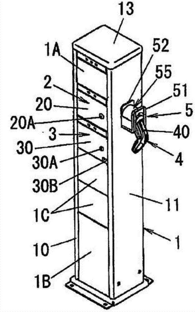
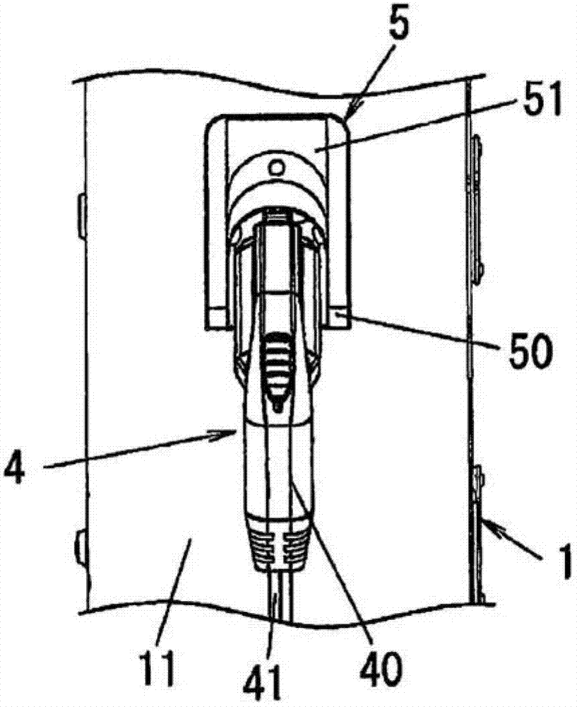
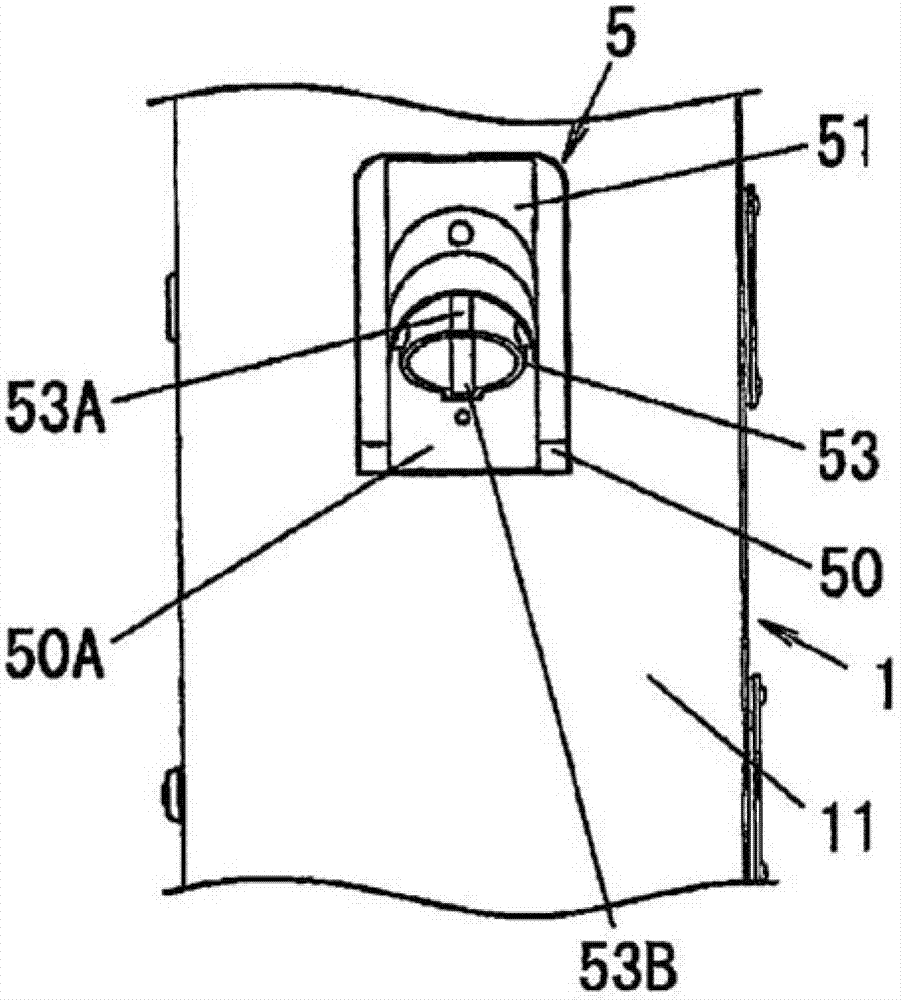

no. 1 example )

[0025] Hereinafter, an electric vehicle charging station according to a first embodiment of the present invention will be described in detail with reference to the accompanying drawings. Please note that in the following descriptions, unless otherwise specified, the up-down and left-right directions are based on Figure 2A The directions shown in are defined, and the front-to-back directions are in Figure 2C is limited to the left-right direction. In addition, in Figure 1A , Figures 2A to 2E as well as Figure 6B The cable 41 is omitted in .

[0026] The electric vehicle charging station according to this embodiment includes a box-shaped body 1; a power supply unit (power transmission unit) 2 housed in said body 1, which is used to transmit electric energy to a battery for connecting to an electric vehicle (not shown). The charging cable 4 of the power transmission path; and the socket unit (power transmission unit) 3 . Furthermore, in this embodiment, a holder 5 for ...

no. 2 example )

[0051] Thereafter, reference will be made to Figure 7A 9 to 9 describe in detail the electric vehicle charging station according to the second embodiment of the present invention. Note that since the second embodiment basically has the same structure as the first embodiment, the same reference numerals are assigned to the same components and redundant descriptions thereof are omitted.

[0052] In this embodiment, it is assumed that the outlet unit 3 does not include the built-in CCID 200 . Such as Figure 8 As shown, the charging cable 4 of this embodiment includes a charging gun 40 , a cable 41 , a power plug 42 and a CCID 43 . Such as Figure 9A As shown, CCID 43 includes a rectangular housing 430 within which terminal modules 201 and 202 , control circuit 203 , and relay 204 are housed. That is, the CCID 43 has the same configuration as the CCID 200 of the first embodiment except for the housing 430 .

[0053] Such as Figure 8 As shown, the CCID 43 is placed in the ...


PUM


Abstract

The invention relates to a charging station for an electric vehicle, comprising: a box-shaped body; and a power transmission unit accommodated in the body. The power transmission unit is used for transmitting electric energy to a charging cable, wherein the charging cable is used as a power transmission path connected to the electric vehicle. A holding part is disposed at the external side of the body, and used for holding at least one part, except the cable of the electric vehicle, of the charging cable. Correspondingly, the part of the charging cable can be held without reduction of the amount of the power transmission units capable of being accommodated in the body.

Description

technical field [0001] The invention relates to a charging station for electric vehicles. Background technique [0002] Recently, electrically driven vehicles such as electric vehicles, electric motorcycles, or plug-in hybrid vehicles (hereinafter, also referred to as “electric vehicles”) have been widely used. As electric vehicles are widely used, charging stations for charging auxiliary batteries installed in electric vehicles are being adopted. A conventional charging station is disclosed in Japanese Laid-Open Patent Application Publication No. 2010-277855 (JP 2010-277855A). [0003] The conventional charging station disclosed in JP2010-277855A includes: a body with a plurality of accommodating spaces inside the body, and the body is vertically installed on the ground where the electric vehicle will be parked; and the accommodating spaces of the body A cabinet contained within that holds the containers. [0004] In this conventional charging station, if the cable const...

Claims


Application Information

Patent Timeline
Patent Type & Authority Patents(China)
IPC IPC(8): H02J7/00
CPCY02T10/7005Y02T10/70Y02T10/7072Y02T90/12Y02T90/14B60L53/16B60L53/30H02J7/0042
Inventor 田中昌史渡边旭
Owner PANASONIC INTELLECTUAL PROPERTY MANAGEMENT CO LTD
Learn More