Heat sink
A radiator and cooling fin technology, applied in the directions of radiators, indirect heat exchangers, heat transfer modification, etc., can solve the problems of poor cooling efficiency, little improvement in cooling efficiency, and difficult air circulation, so as to improve the cooling efficiency. performance, the effect of reducing the number of fins
- Summary
- Abstract
- Description
- Claims
- Application Information
AI Technical Summary
Problems solved by technology
Method used
Image
Examples
Embodiment 1
[0042] (Example 1, Comparative Example 1)
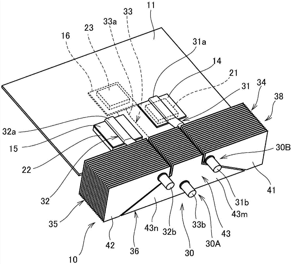
[0043] figure 1 It is a perspective view which shows the heat sink 10 (Example 1) of this invention.
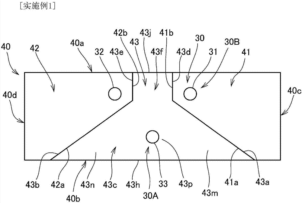
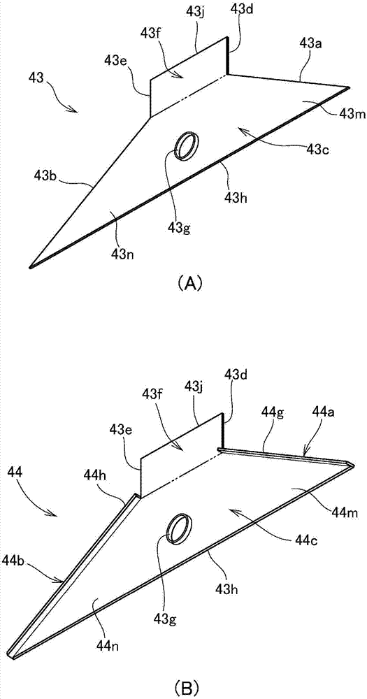
[0044]The heat sink 10 is composed of heat receiving plates 14 , 15 , a heat receiving plate 16 , heat pipes 31 , 32 , 33 , and radiating fin portions 34 , 35 , 36 . The element 21 and the second element 22 are thermally connected respectively, the heat receiving plate 16 is thermally connected to the third element 23 disposed on the lower surface of the substrate 11, and the one ends 31a, 32a, 33a of the heat pipes 31, 32, 33 are covered by Attached to these heat receiving plates 14, 15, 16, the said heat radiation fin part 34, 35, 36 is attached to the other end part 31b, 32b, 33b side of each of these heat pipes 31, 32, 33 respectively. The radiating fin parts 34 , 35 , 36 constitute a radiating part 38 whose overall external shape is formed into a substantially cuboid shape, and each of the radiating fin parts 34 , 35 , 36 is...
Embodiment 2
[0074] Figure 5 It is a perspective view showing the heat sink 50 (Example 2) of this invention. right with figure 1 The same structures as those shown in Embodiment 1 are given the same reference numerals, and detailed descriptions are omitted.
[0075] The radiator 50 is different from the radiator 10 only in the heat dissipation fin parts 54, 55, 56 (refer to figure 1 ) of the cooling fins 34, 35, 36 (refer to figure 1 ). That is, the radiator 50 is constituted by the heat receiving plates 14 , 15 , 16 , the heat pipes 31 , 32 , 33 , and the radiating fin portions 54 , 55 , 56 . The three radiating fin parts 54 , 55 , 56 constitute a radiating part 58 whose overall shape is substantially rectangular parallelepiped, and each of the radiating fin parts 54 , 55 , 56 is composed of a plurality of fin plates 61 , 62 , 63 .
[0076]The fin plate 63 arranged on the heat pipe 33 in the center among the three heat pipes 31 , 32 , and 33 is formed in a triangular shape.
[...
experiment example
[0088] Regarding Example 1, Example 2, and Comparative Example 1 shown above, the relationship between the area and shape of the fin plate and the temperature of the element was evaluated under the following experimental conditions. Table 1 shows the evaluation results.
[0089] ·Experimental conditions
[0090] (a) Calorific value and size of components
[0091] First component: 15W, 20mm×15mm
[0092] Second component: 15W, 30mm×30mm
[0093] The third component: 25W, 20mm×20mm
[0094] A sample element in which a ceramic heater (MS-1, manufactured by Sakaguchi Electric Heating Co., Ltd.) was mounted on a copper block of the above-mentioned size was used for all measurements.
[0095] (b) Wind speed of cooling air flowing from top to bottom on each fin: 1.5m / s
[0096] (c) Thermal conductivity of thermally conductive grease between the element and the heating plate: 6W / mK
[0097] (d) Heating plate: size 30mm×30mm, plate thickness 1mm, material is nickel-plated aluminu...
PUM
 Abstract
Description
Claims
Application Information
 - R&D
- Intellectual Property
- Life Sciences
- Materials
- Tech Scout
- Unparalleled Data Quality
- Higher Quality Content
- 60% Fewer Hallucinations
Browse by: Latest US Patents, China's latest patents, Technical Efficacy Thesaurus, Application Domain, Technology Topic, Popular Technical Reports.
© 2025 PatSnap. All rights reserved.Legal|Privacy policy|Modern Slavery Act Transparency Statement|Sitemap|About US| Contact US: help@patsnap.com


