
Edging roll device of rolling mill

An edge-rolling and edge-rolling technology is applied in the field of metal strip rolling equipment, which can solve the problems of large fluctuation in the width of the edge roll, difficult to control the expansion, and difficult to eliminate the internal force, so as to achieve small fluctuation of the expansion and easy control. , the effect of reducing the number of

Active Publication Date: 2015-03-04
ANHUI CHUJIANG TECHCAL NEW MATERIAL CO LTD
View PDF7 Cites 0 Cited by
  • Summary
  • Abstract
  • Description
  • Claims
  • Application Information

AI Technical Summary

Problems solved by technology

[0003] In the actual use of the existing edging roller device, due to the pulling effect of the back tension of the edging roller, the roller often slips during the rolling process of dragging the metal strip. Only by reducing the number of edging rollers can the edging be realized. , the number of edge rolls is small, the width fluctuates greatly, and the width is difficult to control
[0004] If the motor drive for edge rolling is not stopped after the roll bites into the copper strip, and the back tension of the edge rolling roll is reduced, it will be difficult to match the speed due to the forward slip and backward slip in the rolling and edge rolling process, resulting in a large The internal force is difficult to eliminate, resulting in equipment damage
It is difficult to realize active driving of rolls and edge rolls at the same time without interaction during rolling

Method used


Image

  • Edging roll device of rolling mill
  • Edging roll device of rolling mill

Examples


Embodiment Construction

[0014] The specific implementation manner of the present invention will be described in further detail below by describing the embodiments with reference to the accompanying drawings.

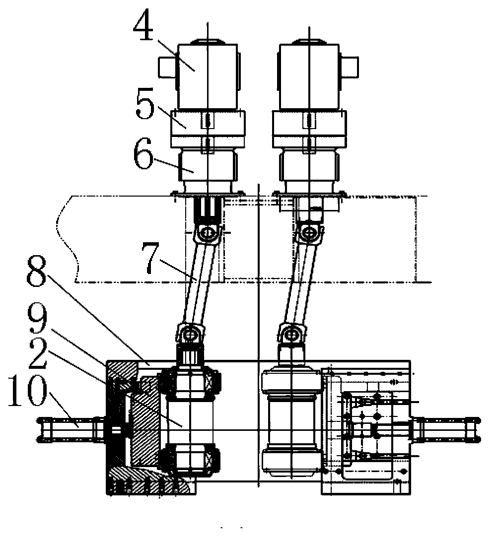
[0015] Such as figure 1 and figure 2 As shown, an edger roller device of a rolling mill includes an edger motor 4, an overrunning clutch 5, a speed reducer 6, a universal coupling 7, an edger roller 2, an edger motor and an overrunning clutch, an overrunning clutch and a reducer They are all connected by transmission shafts, the reducer is fixed on the top of the rolling mill archway through the flange, the edge roll 2 is set on the edge roll stand 8, the reducer and one end of the edge roll are connected through a universal coupling connect.

[0016] Further, the device also includes an edge roll gap adjustment mechanism, the edge roll gap adjustment mechanism includes a hydraulic cylinder 10, a bearing seat, and a bearing, and the two ends of the edge roll 2 are arranged on the bearing sea...


PUM


Abstract

The invention discloses an edging roll device of a rolling mill. The edging roll device comprises edging motors, speed reducers and edging rolls connected with the speed reducers. The edging rolls are arranged on an edging roll base, and an overrunning clutch is arranged between each edging motor and the corresponding speed reducer. Owning to the overrunning clutch added between each edging motor and the corresponding speed reducer, a strip stops advancing and the overrunning clutches are closed once the strip slip from the rolls, and the edging rolls are driven to edge actively and feed the strip to the rolls forcedly; once the strip is engaged and rolled by the rolls, the overrunning clutches are separated automatically due to the fact that the rolling speed is higher than the edging speed, and thus, damage to equipment due to internal stress generated by mismatching of speeds of the strip drive by the rolling motor and the edging motor is avoided. The rolls and the edging rolls have good synchronism, the quantity of the edging rolls is not required to be reduced, and broadsiding fluctuation of the rolled strip is small and is convenient to control.

Description

technical field [0001] The invention relates to the technical field of metal strip rolling equipment, in particular to an edge roll device of a rolling mill. Background technique [0002] At present, in the hot rolling production of metal strips, especially the hot rolling production of copper strips, the change of width is controlled by using an edge roll device. The existing edging roller device includes a motor, a reducer, a universal coupling, and an edging roller. In the actual rolling process, the edging roller is driven by the edging motor. Side-by-side force feeding to the rolling mill, the rolls of the rolling mill bite into the copper strip and continue rolling, and stop the motor drive of the edging roller, and rely on the biting force of the roll to drag the copper strip forward to achieve edging. [0003] In the actual use of the existing edging roller device, due to the pulling effect of the back tension of the edging roller, the roller often slips during the ...

Claims


Application Information

Patent Timeline
Patent Type & Authority Patents(China)
IPC IPC(8): B21B37/16B21B35/00B21B31/32
Inventor 陈操汤昌东张耀赵金生芮日金
Owner ANHUI CHUJIANG TECHCAL NEW MATERIAL CO LTD
Learn More