
Pile frame lifting operation mechanism
A technology of operating mechanism and pile frame, which is applied in the direction of lifting device, etc., can solve the problems of unfavorable fault detection and elimination, hidden danger of maintenance personnel, and location on the side of the column, etc., so as to improve safe operation performance, convenient and reliable operation, and improve the scope of operation Effect
- Summary
- Abstract
- Description
- Claims
- Application Information
AI Technical Summary
Problems solved by technology
Method used
Image

Examples
Embodiment Construction
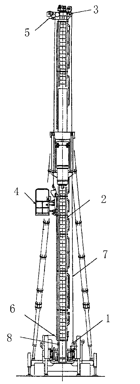
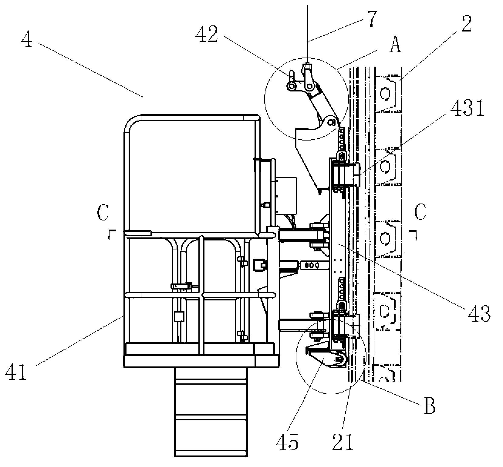
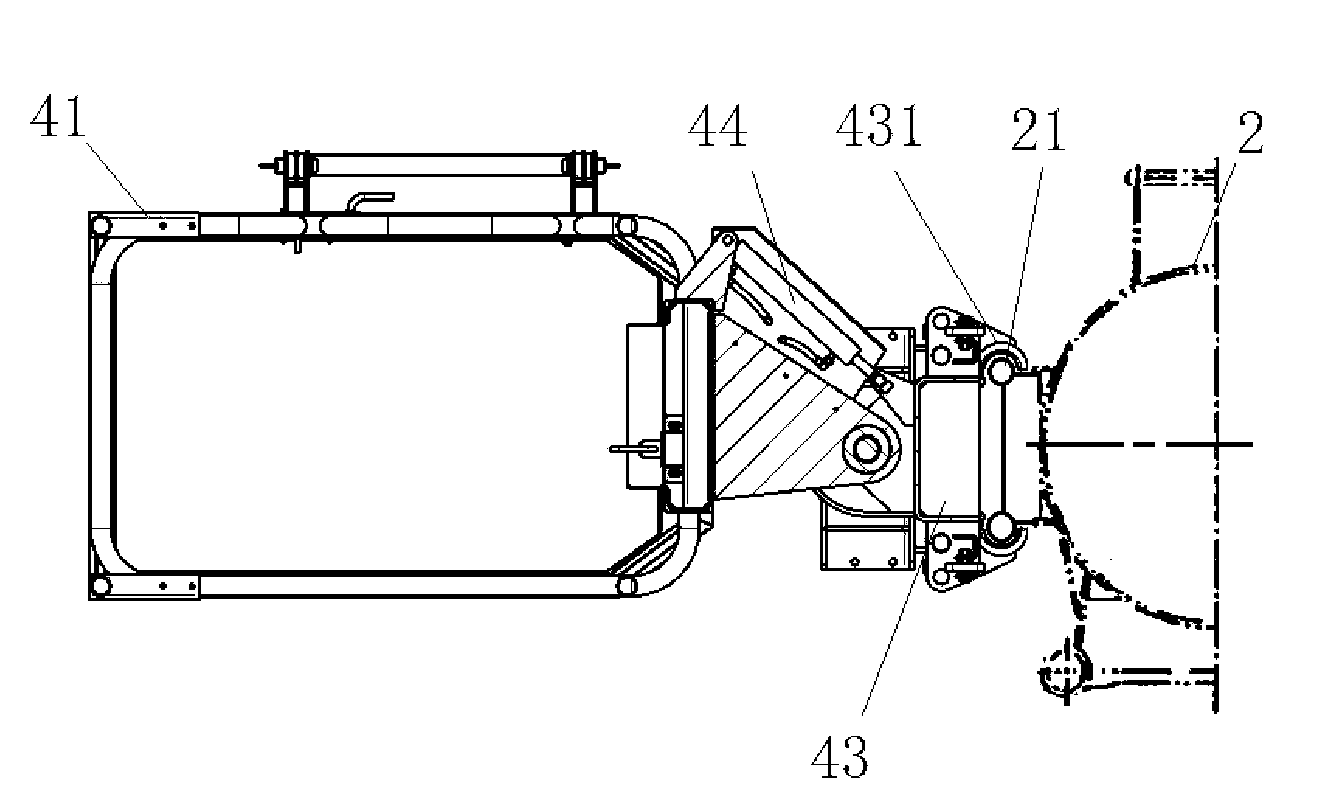
[0021] Such as Figure 1 to Figure 8 As shown, a pile frame lifting operation mechanism includes a hoist unit 1 with a hydraulic motor on the chassis platform, a column 2, a top pulley frame 3, a working cage 4, a hoist over-roll limiter 5, and a hoist over-release limiter. positioner 6, steel wire rope 7, stop block 8 and speed control system 9, wherein, the operation cage 4 includes a cage body 41, a lifting frame 42, a frame 43 and a rotary oil cylinder 44; it is characterized in that: the column 2 There are a pair of side guide rails 21 symmetrically arranged along the axial direction and ribs 22 arranged equidistantly between the pair of guide rails; the top pulley frame 3 is fixed on the top of the column 2 through bolts and nuts; the machine A guide plate 431 is symmetrically arranged on the frame 43, and the operation cage 4 is placed on the side guide rail 21 of the column 2 through the guide plate 431 of the frame 43; the cage body 41 is hingedly connected with the f...
PUM
 Abstract
Description
Claims
Application Information