
Film coating bearing frame

A carrier and tray technology, applied in the direction of sputtering plating, ion implantation plating, vacuum evaporation plating, etc., can solve the problems of inconsistent film characteristics, time-consuming, and inability to maintain completely consistent environmental parameters, etc., to reduce The number of times of heating and vacuuming, and the effect of shortening the coating time

Inactive Publication Date: 2012-11-28
HONG FU JIN PRECISION IND (SHENZHEN) CO LTD +1
View PDF0 Cites 9 Cited by
  • Summary
  • Abstract
  • Description
  • Claims
  • Application Information

AI Technical Summary

Problems solved by technology

[0002] In the existing vacuum coating equipment, only one side of the workpiece to be coated can be coated at a time. If it is necessary to coat both sides of the workpiece to be coated, the vacuum chamber must be opened, and the bearing part carrying the workpiece to be coated must be manually turned over.
This will have the following disadvantages: first, two vacuum pumping operations are required, which is time-consuming; second, the temperature in the vacuum chamber is extremely high during evaporation, so when turning over manually, you must wait until the vacuum chamber cools down. Open the vacuum chamber, take out the carrying part, turn it over and put it into the vacuum chamber, which prolongs the processing time of the coating; thirdly, the vacuum chamber needs to be opened twice, and the environmental parameters in the vacuum chamber cannot be kept completely consistent. This leads to inconsistent film characteristics on both sides of the parts to be plated; fourth, when the vacuum chamber is opened, the cleanliness of the parts to be plated will decrease, which in turn will affect the yield of the parts to be plated

Method used


Image

  • Film coating bearing frame
  • Film coating bearing frame
  • Film coating bearing frame

Examples


Embodiment Construction

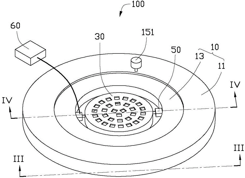
[0013] see figure 1 , is a coating carrier 100 provided in an embodiment of the present invention, which is used to carry a plurality of parts to be coated. The coating carrier 100 includes a base 10 , a carrier plate 30 , a turning assembly 50 and a controller 60 .

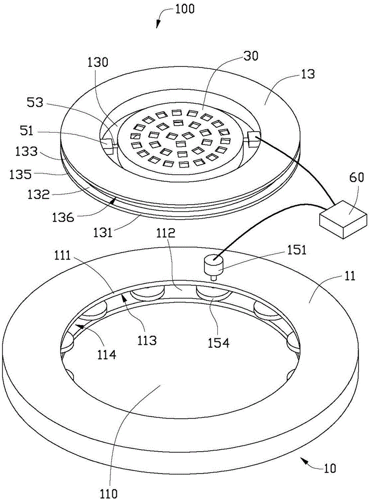
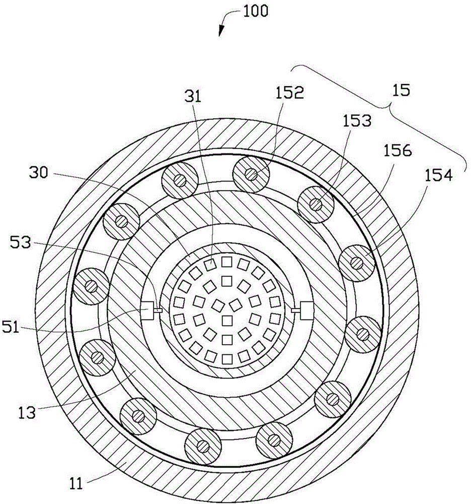
[0014] Such as figure 2 and image 3 As shown, the base 10 includes a disc-shaped outer frame 11 , a disc-shaped inner frame 13 and a rotating assembly 15 .

[0015] The outer frame 11 is fixed in a coating chamber (not shown). The outer frame 11 defines a first through hole 110 around its own center of circle to form a circular inner wall 111 . An accommodating groove 112 is defined on the inner wall 111 along its own circumferential direction. The accommodating groove 112 includes an annular upper surface 113 and an annular lower surface 114 opposite to the upper surface 113 .

[0016] The radius of the inner frame 13 is equal to the inner diameter of the first through hole 110, so that the inner frame 1...


PUM


Abstract

The invention provides a film coating bearing frame, comprising a base, a carrying disc and an overturning assembly, wherein the base comprises an outer frame and a circular-disk-shaped inner frame which is rotatably arranged on the outer frame. The outer frame is provided with a first through hole. The inner frame is contained in the first through hole and is arranged coaxial with the first through hole. The carrying disc is reversibly arranged on the inner frame through the overturning assembly. The carrying disc is provided with a plurality of bearing through holes of bearing pieces to be coated. The overturning assembly comprises two overturning motors and two rotating shafts coupled with the corresponding overturning motors. The two overturning motors are fixedly arranged on the inner frame and are used for driving the corresponding rotating shafts to rotate. The two rotating shafts are oppositely arranged and are located on the same straight line. The opposite two ends of each rotating shaft are respectively fixed on the corresponding overturning motors and the carrying disc. The film coating bearing frame disclosed by the invention utilizes the overturning assembly to automatically overturn the pieces to be coated and the pieces to be coated can be subjected to double-faced film coating without opening a vacuum chamber.

Description

technical field [0001] The invention relates to a coating carrier. Background technique [0002] In the existing vacuum coating equipment, only one side of the workpiece to be coated can be coated at a time. If it is necessary to coat both sides of the workpiece to be coated, the vacuum chamber must be opened, and the bearing part carrying the workpiece to be coated must be manually turned over. . This will have the following disadvantages: first, two vacuum pumping operations are required, which is time-consuming; second, the temperature in the vacuum chamber is extremely high during evaporation, so when turning over manually, you must wait until the vacuum chamber cools down. Open the vacuum chamber, take out the carrying part, turn it over and put it into the vacuum chamber, which prolongs the processing time of the coating; thirdly, the vacuum chamber needs to be opened twice, and the environmental parameters in the vacuum chamber cannot be kept completely consistent. ...

Claims


Application Information

Patent Timeline
IPC IPC(8): C23C14/50
Inventor 裴绍凯
Owner HONG FU JIN PRECISION IND (SHENZHEN) CO LTD
Learn More