Spiral photoresist coating structure and preparation device and method thereof
A spiral, photoresist technology, which is applied in spraying devices, photoplate-making process coating equipment, semiconductor/solid-state device manufacturing, etc., can solve the problems of uneven thickness of photoresist, lack of glue in local areas, high price of photoresist, etc., to achieve The effect of reasonable distribution, reduction of abnormal occurrence, and cost reduction
- Summary
- Abstract
- Description
- Claims
- Application Information
AI Technical Summary
Problems solved by technology
Method used
Image
Examples
Embodiment 1
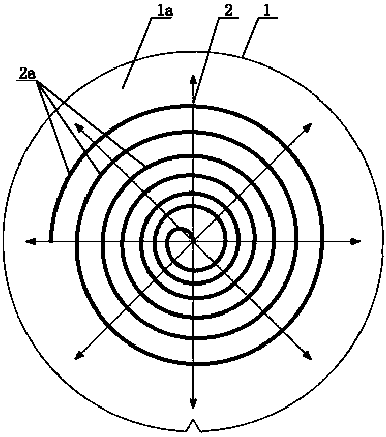
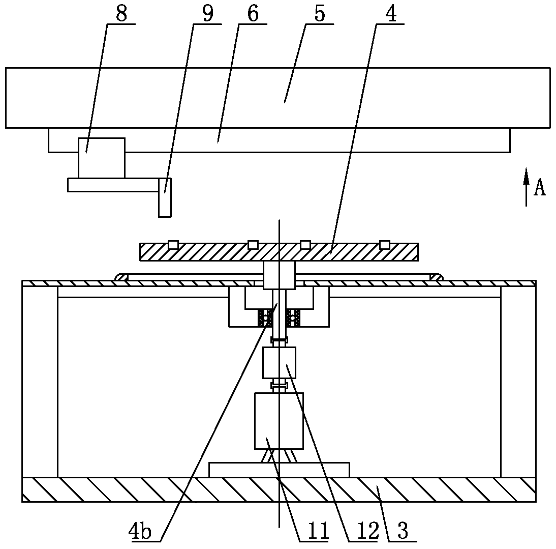
[0026] like Figure 1-5 As shown, it is a spiral photoresist coating structure, including a wafer 1, the surface of the wafer 1 is covered with a processing solvent layer 1a, and a photoresist layer 2 is arranged above the processing solvent layer 1a, and the photoresist layer 2 is in a spiral shape. , the spiral photoresist layer 2 includes several unit segments 2a connected end to end, the tail end of the adjacent outer layer unit segment 2a is connected to the head end of the inner layer unit segment 2a, and the distance between the adjacent two outer unit segments 2a is greater than The distance between two adjacent unit segments 2a on the inner side. The head end and tail end of each unit segment 2 a are located on the same diameter of the wafer 1 . The tail end of the inner unit segment 2a is located at the center of the wafer 1, and the diameter of the wafer 1 is 200mm. The composition and content of the processing solvent of the processing solvent layer 1a are: propy...
Embodiment 2
[0032] Such as Figure 1-5 As shown, it is a spiral photoresist coating structure, including a wafer 1, the surface of the wafer 1 is covered with a processing solvent layer 1a, and a photoresist layer 2 is arranged above the processing solvent layer 1a, and the photoresist layer 2 is in a spiral shape. , the spiral photoresist layer 2 includes several unit segments 2a connected end to end, the tail end of the adjacent outer layer unit segment 2a is connected to the head end of the inner layer unit segment 2a, and the distance between the adjacent two outer unit segments 2a is greater than The distance between two adjacent unit segments 2a on the inner side. The head end and tail end of each unit segment 2 a are located on the same diameter of the wafer 1 . The tail end of the inner unit segment 2a is located at the center of the wafer 1, and the diameter of the wafer 1 is 195mm. The composition and content of the processing solvent of the processing solvent layer 1a are: pr...
Embodiment 3
[0038] Such as Figure 1-5 As shown, it is a spiral photoresist coating structure, including a wafer 1, the surface of the wafer 1 is covered with a processing solvent layer 1a, and a photoresist layer 2 is arranged above the processing solvent layer 1a, and the photoresist layer 2 is in a spiral shape. , the spiral photoresist layer 2 includes several unit segments 2a connected end to end, the tail end of the adjacent outer layer unit segment 2a is connected to the head end of the inner layer unit segment 2a, and the distance between the adjacent two outer unit segments 2a is greater than The distance between two adjacent unit segments 2a on the inner side. The head end and tail end of each unit segment 2 a are located on the same diameter of the wafer 1 . The tail end of the inner unit segment 2a is located at the center of the wafer 1, and the diameter of the wafer 1 is 205 mm. The composition and content of the processing solvent of the processing solvent layer 1a are: 6...
PUM
| Property | Measurement | Unit |
|---|---|---|
| diameter | aaaaa | aaaaa |
Abstract
Description
Claims
Application Information
 - R&D
- Intellectual Property
- Life Sciences
- Materials
- Tech Scout
- Unparalleled Data Quality
- Higher Quality Content
- 60% Fewer Hallucinations
Browse by: Latest US Patents, China's latest patents, Technical Efficacy Thesaurus, Application Domain, Technology Topic, Popular Technical Reports.
© 2025 PatSnap. All rights reserved.Legal|Privacy policy|Modern Slavery Act Transparency Statement|Sitemap|About US| Contact US: help@patsnap.com


