
Integral erection construction method of 60m steel box girder

A construction method and technology of steel box girders, applied in bridge construction, erection/assembly of bridges, bridges, etc., can solve problems such as high safety and quality risks, inability to meet the requirements of large crane construction sites, and large welding workload. Achieve the effects of reducing assembly and welding procedures, facilitating the organization of flow construction, and ensuring quality and safety

Active Publication Date: 2012-11-28
CHINA RAILWAY SIXTH GRP CO LTD
View PDF4 Cites 30 Cited by
  • Summary
  • Abstract
  • Description
  • Claims
  • Application Information

AI Technical Summary

Problems solved by technology

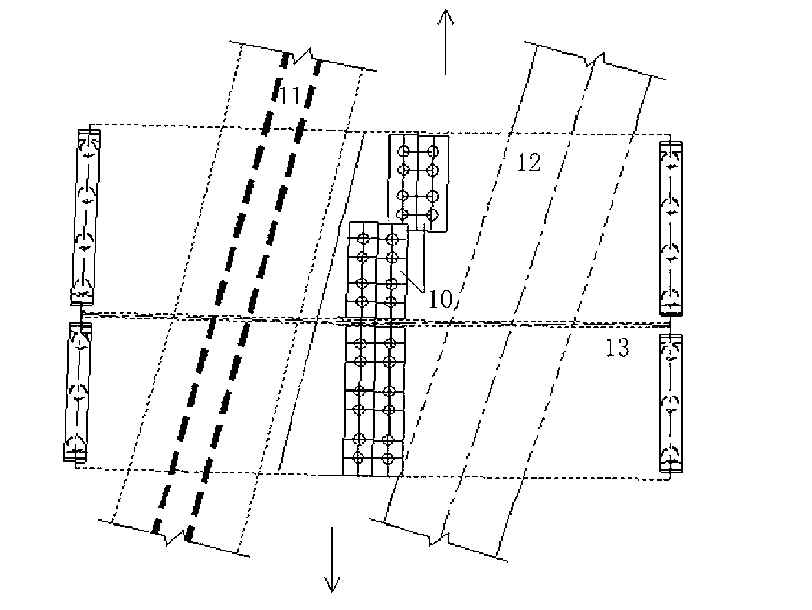
[0009] 2. The traditional steel box girder construction scheme usually uses a crane to hoist in sections, and a temporary pier is set up in the middle to erect the assembled steel box girder sections, and then the steel box girder is longitudinally welded on the temporary pier; however, the two set up in this project The row of temporary buttresses are just located on the national road and directly above the railway. Since the national road cannot be closed, it cannot be completed.
[0010] 3. The steel box girder has a large span of 60 meters, which is rare in my country, and because the span is located on the superelevation section of the R=1500m curve, the safety and quality risks of using the traditional steel box girder erection method are extremely high
[0011] 4. The single-piece steel box girder is heavy, with a maximum weight of 231.35t
[0012] 5. The existing railway and national road are under the bridge to be constructed, and the site is very narrow, which cannot meet the requirements of the construction site for large cranes
[0021] 1. The radius of the hoisting operation is relatively large, and a large-tonnage crane is required for hoisting, which is expensive, and the site is narrow, which cannot meet the requirements of the large-scale crane construction site and cannot be implemented
[0022] 2. It is necessary to set up multiple rows of temporary buttresses above the national road and railway, which will greatly interfere with the construction of the national road and railway. Because the existing national road cannot be closed, it cannot be realized
In addition, the construction of the temporary buttress in the middle will have a great impact and safety risk on the existing railway, highway traffic operation and surrounding structures
[0023] 3. The sections of the steel box girder need to be assembled and welded on the temporary pier, the process is complicated and the construction period is long
[0024] 4. When hoisting and splicing steel box girder sections on the intermediate pier, there may be horizontal impact of the segmented box during the hoisting process, which poses a great safety risk
[0025] 5. Welding the segmented box on the temporary buttress, the welding workload is heavy, the welding time is long, and the construction on busy railway lines and national highways will increase the unsafe factors.

Method used


Image

  • Integral erection construction method of 60m steel box girder
  • Integral erection construction method of 60m steel box girder
  • Integral erection construction method of 60m steel box girder

Examples


Embodiment Construction

[0099] The specific embodiment of the present invention will be further described in conjunction with the accompanying drawings.

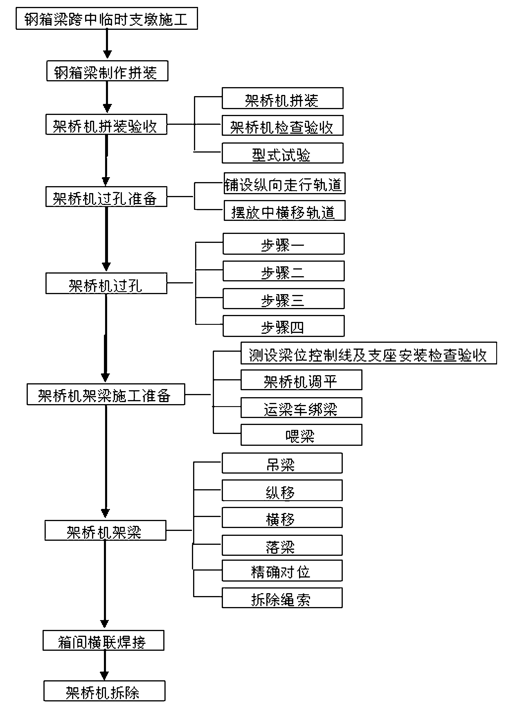
[0100] The construction method of the overall erection of 60m steel box girder is carried out by using the fasting box-shaped double-girder bridge erecting machine. Hole construction preparation → bridge erecting machine passing the hole → bridge erecting frame girder construction preparation → bridge erecting frame girder → cross connection welding between boxes → bridge erecting machine dismantling, such as figure 1 shown.

[0101] Taking the project described in the background technology as an example, the specific steps are as follows:

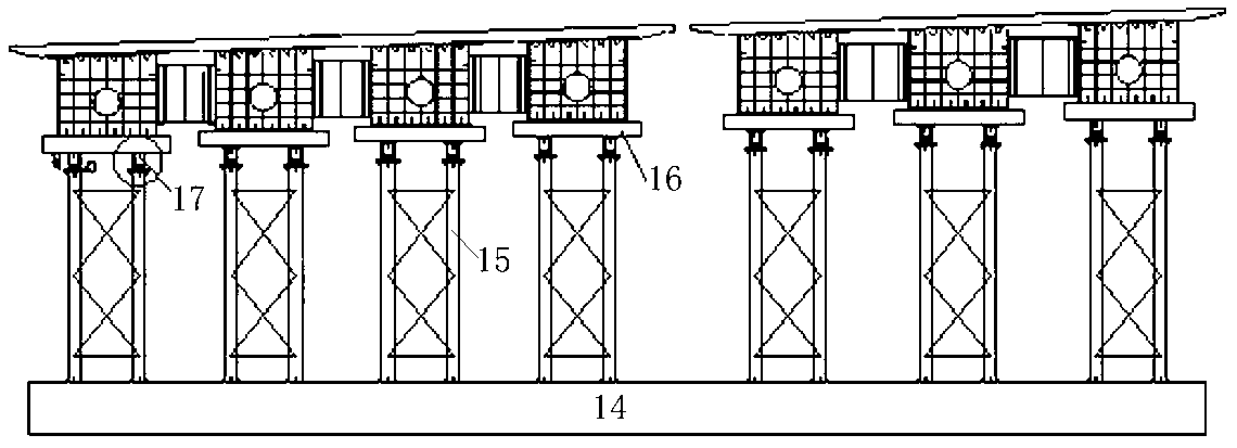
[0102] 1. Construction of temporary buttresses in the mid-span of steel box girders

[0103] Since the 60m steel box girder is a steel-concrete composite girder, the joint force can only be exerted after the concrete pouring of the bridge deck is completed. Therefore, when the steel box girder is erected by a...


PUM


Abstract

The invention belongs to the technical field of the construction of large bridge bodies, and specifically relates to an integral erection construction method of a 60m steel box girder, which reduces the influence of the construction of long-span steel box girders to communications and transportation and surrounding structures. The method comprises the following steps of: midspan construction of temporary pillar of steel box girder, steel box girder assembling manufacturing, bridge girder erection machine assembling and checking, hole passing of the bridge girder erection machine, preparation for girder erection of the bridge girder erection machine girder and girder erection, transverse welding among boxes, and bridge girder erection machine dismantling. In the method, a hollow box-shaped double-beam bridge girder erection machine is used for carrying out the construction of the steel box girder so as to efficiently solve the construction problem that the 60m and 230t steel box girder simultaneously spans over railways and roads; and the method ensures the operation safety of the conventional railways and national roads and minimizes the influence of the construction to railways and national roads.

Description

technical field [0001] The invention belongs to the technical field of installation and construction of large bridge girders, and in particular relates to a construction method for the integral erection of a 60-meter steel box girder. Background technique [0002] With the rapid development of my country's iron and steel industry and steel structure technology, the number of steel structure bridges is also increasing. The steel box girder structure has a large span, long service life, high torsional rigidity of the box section, small section height, and good integrity. The characteristics make the steel box girder structure widely used in the design and construction of municipal and highway bridges, and has become the first choice for long-span main girders. Due to the development of bridge technology and the requirements of traffic guidance, the span of urban steel box girders is also increasing, and shows a trend of substantial growth; at the same time, due to the complexit...

Claims


Application Information

Patent Timeline
Patent Type & Authority Applications(China)
IPC IPC(8): E01D21/06
Inventor 郝晋新杜永清黄枝花刘训炬佟垚周培培许月香李旭东李俊有
Owner CHINA RAILWAY SIXTH GRP CO LTD
Learn More