Micro solenoid valve with low power consumption

A solenoid valve, low power consumption technology, applied in the field of solenoid valves, can solve the problems of small medium flow, high working temperature, complex structure, etc., and achieve the effect of increasing medium flow, reducing power consumption, and simplifying the overall structure

Inactive Publication Date: 2012-11-28
李景峰
View PDF0 Cites 4 Cited by
  • Summary
  • Abstract
  • Description
  • Claims
  • Application Information

AI Technical Summary

Problems solved by technology

[0002] Miniature solenoid valves are the key executive components of automatic control. Due to design and structural reasons, miniature solenoid valves currently used in the market generally have shortcomings such as high working temperature, small medium flow rate, large power consumption, and complex structure.

Method used


Image

  • Micro solenoid valve with low power consumption
  • Micro solenoid valve with low power consumption
  • Micro solenoid valve with low power consumption

Examples


Embodiment 1

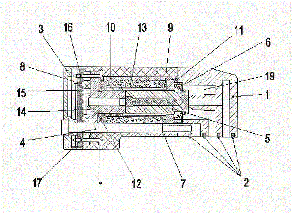
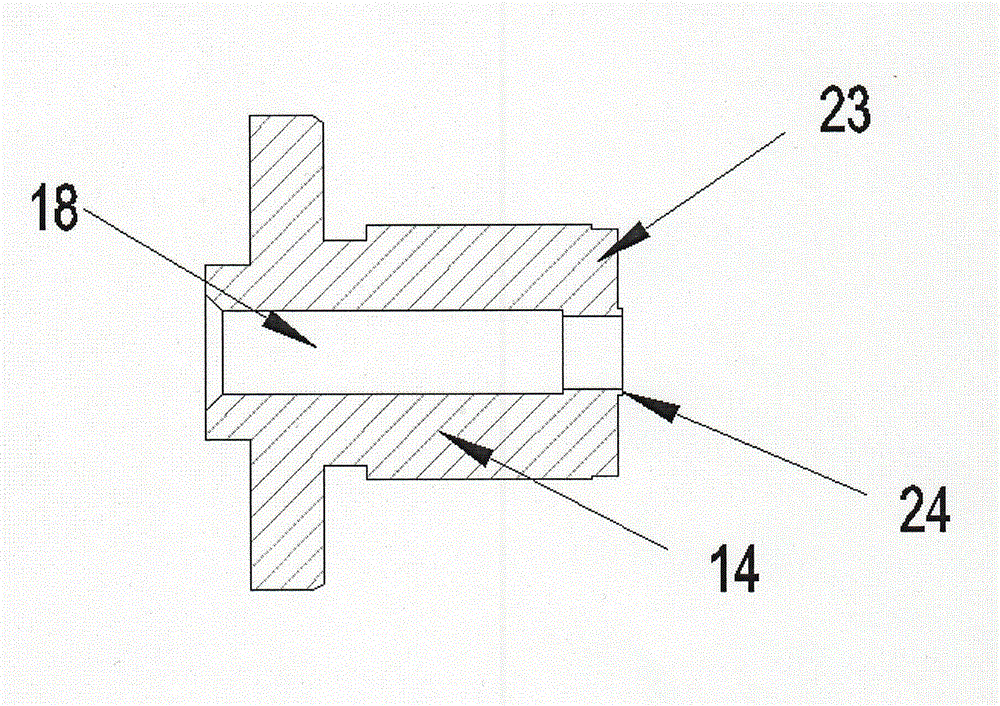
[0014] Embodiment 1: as figure 1 As shown, the low-power miniature solenoid valve includes valve body 1, valve body sealing ring 2, end cover 3, fastening screw 4, moving iron core 5, moving iron core spring 6 and electromagnetic coil assembly 7, electromagnetic coil assembly 7 includes circuit board 8, coil O-ring 9, fixed sleeve 10, fixed sleeve O-ring 11, skeleton 12, enameled wire 13, static iron core 14, static iron core O-ring 15, connecting pin 16 and pin 17. The circuit board 8 adopts a pulse circuit control chip. One end of the pulse circuit control chip circuit board 8 is connected to the enameled wire 13 through the connection pin 16, and the other end is connected to the external power supply through the pin 17, such as figure 2 As shown, an exhaust hole 18 is arranged at the center of the static iron core 14, and one end of the exhaust hole 18 is connected with the electromagnetic valve cavity 19, and the other end is connected with the atmosphere, as image 3 A...

Embodiment 2

[0016] Embodiment 2: The outer diameter of the static iron core 14 is 8.4 mm, and the end of the small head 23 of the static iron core is provided with a sealing boss 24 of ф1.54 and 0.5 mm in height, and the rest are the same as in the embodiment 1.

Embodiment 3

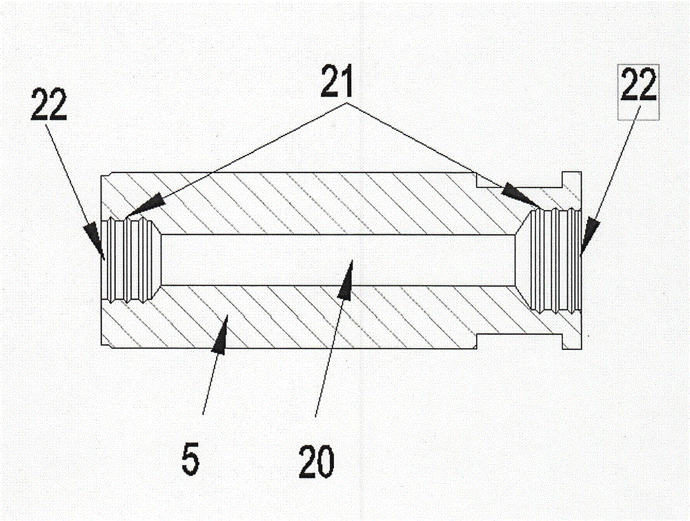
[0017] Embodiment 3: The outer diameter of the moving iron core 5 is 4.5mm, and there is a through hole 20 inside. The two ends of the through hole 20 are respectively connected to the large holes 22 with ф2.5 and ф2 and five anti-skid grooves 21 inside, and the rest are the same as in Embodiment 1. .


PUM


Abstract

The invention discloses a micro solenoid valve with low power consumption. The micro solenoid valve comprises a valve body, valve body seal rings, an end cover, a fastening bolt, a movable iron core, a movable iron core spring and an electromagnetic coil assembly, wherein the electromagnetic coil assembly comprises a circuit board, an O-shaped coil ring, a fixing sleeve, an O-shaped fixing sleeve ring, a skeleton, an enameled wire, a fixed iron core, an O-shaped fixed iron core ring, a wire-connection contact pin and a contact pin; a pulse circuit control chip is adopted in the circuit board, one end of the circuit board of the pulse circuit control chip is connected with the enameled wire through the wire-connection contact pin, and the other end of the circuit board is connected with an external power source through the contact pin; and a vent hole is formed in the center of the fixed iron core, one end of the vent hole is communicated with the inner cavity of the solenoid valve, and the other end of the vent hole is communicated with the atmosphere. The micro solenoid valve has the advantages of reasonable structure, high flow rate, obvious energy-saving effect, accurate action, convenience in installation and the like.

Description

technical field [0001] The invention relates to a solenoid valve, in particular to a miniature solenoid valve. Background technique [0002] Miniature solenoid valve is the key executive component of automation control. Due to design and structural reasons, miniature solenoid valves currently used in the market generally have shortcomings such as high working temperature, low medium flow rate, large power consumption, and complex structure. Contents of the invention [0003] The purpose of the present invention is to provide a low power consumption miniature solenoid valve with reasonable structure, large flow rate, remarkable energy-saving effect, accurate action and convenient installation. [0004] In order to achieve the above object, the present invention is achieved through the following technical solutions. Miniature solenoid valve with low power consumption, including valve body, valve body sealing ring, end cover, fastening screw, moving iron core, moving iron co...

Claims


Application Information

Patent Timeline
Patent Type & Authority Applications(China)
IPC IPC(8): F16K31/06
Inventor 李景峰
Owner 李景峰
Why Eureka
Try Eureka