Plasma concave-cavity flame stabilizer for engine

A plasma and burner technology, applied in the application field of aerospace power system, can solve the problems of narrow application range, self-excited oscillation, large cavity resistance, etc., and achieve enhanced injection fuel activity, rapid response and control, small price effect

Inactive Publication Date: 2012-11-28
PLA PEOPLES LIBERATION ARMY OF CHINA STRATEGIC SUPPORT FORCE AEROSPACE ENG UNIV
View PDF6 Cites 25 Cited by
  • Summary
  • Abstract
  • Description
  • Claims
  • Application Information

AI Technical Summary

Problems solved by technology

[0013] The purpose of the present invention is to solve the problems of self-excited oscillation, large cavity resistance and narrow application range in conventional concave cavity flame stabilizers, and propose a new type of engine plasma concave cavity flame stabilizer

Method used


Image

  • Plasma concave-cavity flame stabilizer for engine
  • Plasma concave-cavity flame stabilizer for engine
  • Plasma concave-cavity flame stabilizer for engine

Examples


Embodiment Construction

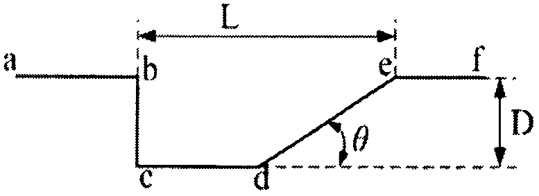
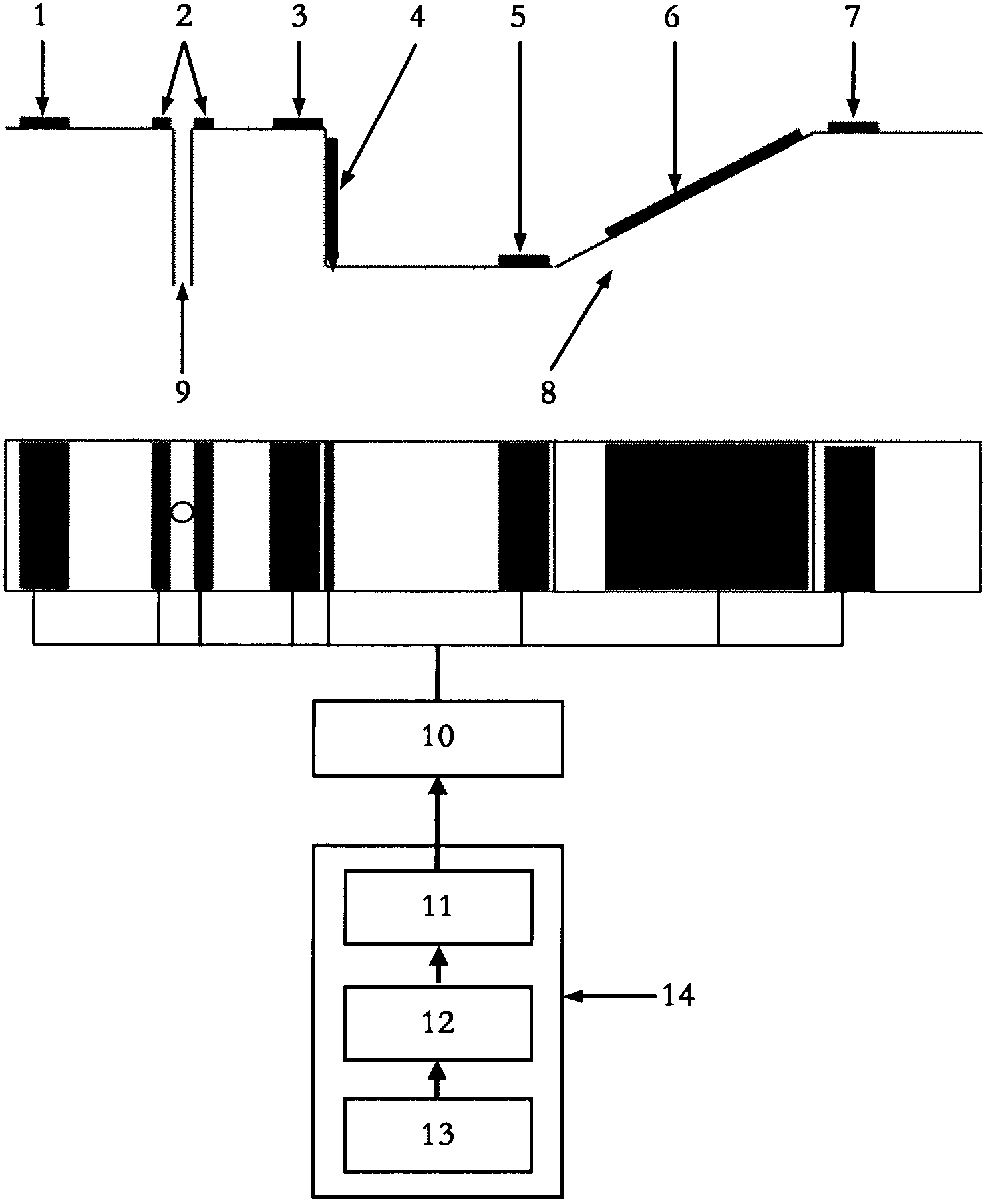
[0031] The engine plasma concave cavity burner of the present invention will be described in detail below in conjunction with the accompanying drawings and embodiments. figure 2 A schematic structural diagram of the engine plasma cavity burner stabilizer of the present invention is given. The concave cavity flame stabilizer of engine plasma of the present invention comprises conventional concave cavity flame stabilizer, and described conventional concave cavity flame stabilizer comprises upstream ab, concave cavity body bcde and downstream ef (see figure 1 ), figure 1 A schematic diagram of the structure of a conventional concave flame holder is given, the upstream ab, the front wall of the cavity bc and the bottom cd of the cavity form a backward step, the bottom cd of the cavity, the rear wall de and the downstream ef form a forward step, and the front wall bc , the bottom wall cd and the rear wall de constitute the concave cavity body bcde, and the angle between the rear ...


PUM


Abstract

The invention belongs to the technical field of application for aeronautic and astronautic power system, and relates to a flame stabilization technology for the combustion chamber of an engine based on a concave-cavity flame stabilizer, aiming at solving the problem of self-excited oscillation existing in conventional concave-cavity flame stabilizers. According to the invention, plasma exciters are installed at the upstream, the front wall, the bottom wall, the rear wall, the downstream and the flue nozzle of a conventional concave-cavity flame stabilizer; the plasma exciters are used for generating unbalanced plasmas via air discharge; and the electric field force inductively generated by the unbalanced plasmas and the released heat generate a control effect on a concave-cavity flow field so as to reduce concave-cavity resistance and suppress concave-cavity self-excited oscillation, and generate activation effects such as excitation, dissociation and ionization on an injected fuel so as to further increase combustion efficiency.

Description

technical field [0001] The invention belongs to the technical field of application of aerospace power systems, and relates to a plasma combustion stabilizing technology in a combustion chamber of an engine based on a concave cavity flame stabilizer. Background technique [0002] The rapid development of the aerospace field requires aircraft to fly faster and farther at a more economical price, which puts forward higher requirements for the propulsion device of the aircraft, especially for scramjet engines and combined engines, combustion The airflow velocity in the chamber can often reach thousands of meters per second, and the length of the combustion chamber cannot be very long due to factors such as weight, size, heat protection, etc., resulting in a very short residence time of the fuel in the supersonic combustion chamber. Therefore, how to realize high-efficiency mixing and stable combustion in the supersonic combustion chamber is one of the most important key technolo...

Claims


Application Information

Patent Timeline
IPC IPC(8): F23R3/22
Inventor 聂万胜车学科田希晖何浩波冯伟苏凌宇侯志勇程钰锋丰松江冯必鸣周思引
Owner PLA PEOPLES LIBERATION ARMY OF CHINA STRATEGIC SUPPORT FORCE AEROSPACE ENG UNIV
Why Eureka
Try Eureka