Thermal shock test system

A test system and thermal shock technology, applied in the detection field, can solve the problems of no toxic and harmful waste gas treatment, retrieved waste gas treatment technology, toxic and harmful waste gas, etc., and achieve the effect of good dynamic response, light weight and high degree of purification

Inactive Publication Date: 2012-11-28
SHANGHAI INST OF QUALITY INSPECTION & TECHN RES
View PDF9 Cites 7 Cited by
  • Summary
  • Abstract
  • Description
  • Claims
  • Application Information

AI Technical Summary

Problems solved by technology

Similar to the previously described situation, a lot of toxic and harmful exhaust gas will be produced after the lithium-ion battery explodes; the exhaust gas is not only poisonous and harmful, polluting the environment, but also not easy to be completely emitted from the indoor to the outdoor, after each lithium-ion battery explosion in the test , the staff have to endure the unpleasant smell for a long time
[0005] However, none of the existing testing equipment has a device for treating the above-mentioned toxic and harmful waste gas; we have entrusted a professional organization to search, and we have not found the waste gas treatment technology of the relevant testing equipment in the published literature.

Method used


Image

  • Thermal shock test system
  • Thermal shock test system
  • Thermal shock test system

Examples


Embodiment 1

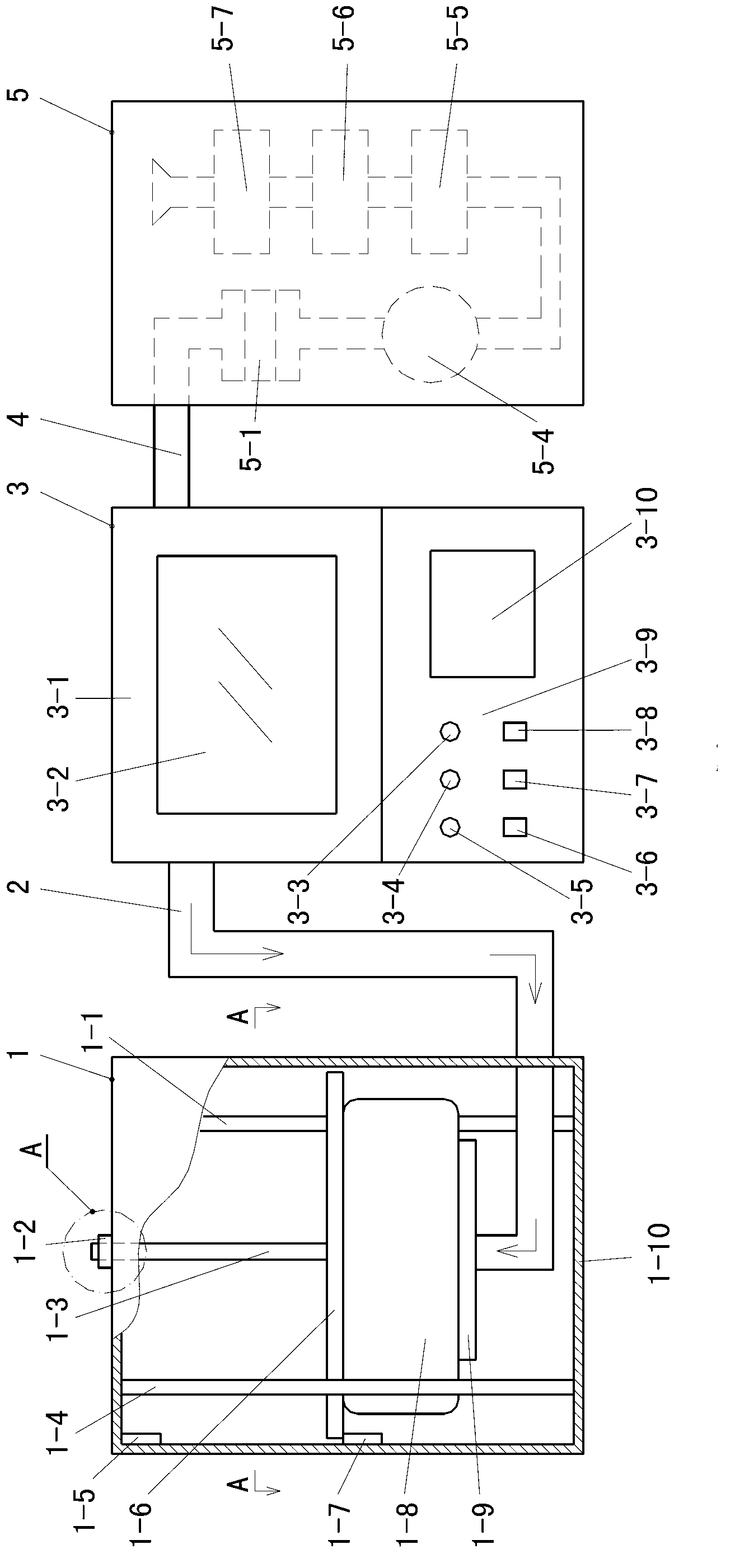
[0187] This embodiment combines figure 1 , Figure 15 and Figure 16 Be explained.

[0188] figure 1 Part of the label description: 1 is the waste gas storage tank; 2 is the first pipeline; 3 is the high temperature test chamber; 4 is the second pipeline; 5 is the waste gas filter box.

[0189] The high-temperature test box 3 has a mechanical structure with good sealing performance, thermal insulation performance and explosion-proof performance. The high temperature test chamber 3 has two functional areas, the upper and the lower.

[0190] In the functional area of ​​the lower part, a control panel 3-9 is installed at its front position, and an automatic control circuit is installed inside it. The automatic control circuit takes the single-chip microcomputer as the core, that is, the automatic control circuit adopts the control technology of the computer, and the software program required by the system of the present invention has been input into the inside of the single-...

Embodiment 2

[0205] In embodiment one, following action is arranged: "When pressing down side limit switch 1-7 again from counterweight plate 1-6, the software program of computer starts counting, and when the pre-set time expires, automatic The control circuit instructs the solenoid valve 3-15 to turn on the driving power, the solenoid valve 3-15 is opened, and new air enters."

[0206] Now, the above action is modified as follows: when the counterweight plate 1-6 presses the lower limit switch 1-7 again, the automation control circuit immediately instructs the solenoid valve 3-15 to turn on the driving power, and the solenoid valve 3-15 opens , new air enters.

Embodiment 3

[0208] In the first embodiment, the high temperature test chamber 3 has two functional areas, the upper and lower; in the third embodiment, the two functional areas are separately separated and set as the high temperature test chamber 3 and the control box.

[0209] The details of the high temperature test box 3 and the control box of the present embodiment are as follows.

[0210] The control box is equipped with a control panel at its front position, and an automatic control circuit is installed inside it. The automatic control circuit takes the single-chip microcomputer as the core, that is, the automatic control circuit adopts the control technology of the computer, and the software program required by the system of the present invention has been input into the inside of the single-chip microcomputer and has been debugged; computer.

[0211] The high temperature test chamber 3 is provided with a high temperature test chamber 3-13, and the tested test sample is placed in t...


PUM


Abstract

The invention relates to the technical field of detection and discloses a thermal shock test system. In order to solve the problem about waste gas treatment, the invention provides the technical scheme as follows: the system comprises a high-temperature test box (3) and the like, and is characterized by also comprising a waste gas storage box (1), a waste gas filtering box (5) including a rough filtration device (5-1), a first pipeline (2) and a second pipeline (4), wherein the waste gas storage box (1) comprises a waste gas box body (1-10), a guide block (1-2) with a guide hole, a guide bar (1-3), a counterweight plate (1-6), a gas bag (1-8) and a mounting plate (1-9); one end of the first pipeline (2) is communicated with a high-temperature test cavity (3-13) and the other end of the first pipeline (2) is communicated with the inside of the gas bag (1-8) through the mounting plate (1-9); and one end of the second pipeline (4) is communicated with the high-temperature test cavity (3-13) and the other end of the second pipeline (4) is communicated with the input port of the rough filtration device (5-1). The thermal shock test system has the beneficial effect that waste gas can be purified during the thermal shock test.

Description

technical field [0001] The invention relates to the technical field of detection, in particular to a thermal shock test system. Background technique [0002] Safe storage and safe use in a higher temperature environment are the technical performances that many products must possess. For this reason, whether it is the manufacturer or the country's special testing agency, it is necessary to conduct thermal shock tests on such products to test and verify The technical performance of the product's resistance to thermal shock. In the thermal shock test, the sample to be tested is often placed in a high-temperature box. After closing the door lock of the high-temperature box, the electric heating circuit is turned on to make the temperature in the high-temperature box gradually increase according to regulations, and the temperature rises in the high-temperature box. The tested sample is tested during the rising process. [0003] During the above-mentioned temperature rise detect...

Claims


Application Information

Patent Timeline
Patent Type & Authority Applications(China)
IPC IPC(8): G01R31/00B01D46/00B01D46/12
Inventor 贺晓笙韦莉陈瑛黄涵韬
Owner SHANGHAI INST OF QUALITY INSPECTION & TECHN RES
Why Eureka
Try Eureka