3D (three-dimensional) display device and glasses matched with same

A display device and 3D technology, applied in the field of glasses, can solve the problems of reducing 3D display effect, picture color distortion, loss of resolution, etc., and achieve the effect of good user experience, no screen flicker, and no loss of resolution.

Active Publication Date: 2012-11-28
BOE TECH GRP CO LTD +1
View PDF5 Cites 16 Cited by
  • Summary
  • Abstract
  • Description
  • Claims
  • Application Information

AI Technical Summary

Problems solved by technology

Among them, polarized light 3D display technology generally adopts the method of dividing space, so half of the resolution will be lost, the effect of 3D display will be reduced, the viewing angle will also be affected and crosstalk (that is, ghost phenomenon) will be easily caused; shutter 3D display technology generally adopts The metho

Method used


Image

  • 3D (three-dimensional) display device and glasses matched with same
  • 3D (three-dimensional) display device and glasses matched with same
  • 3D (three-dimensional) display device and glasses matched with same

Examples


Embodiment 1

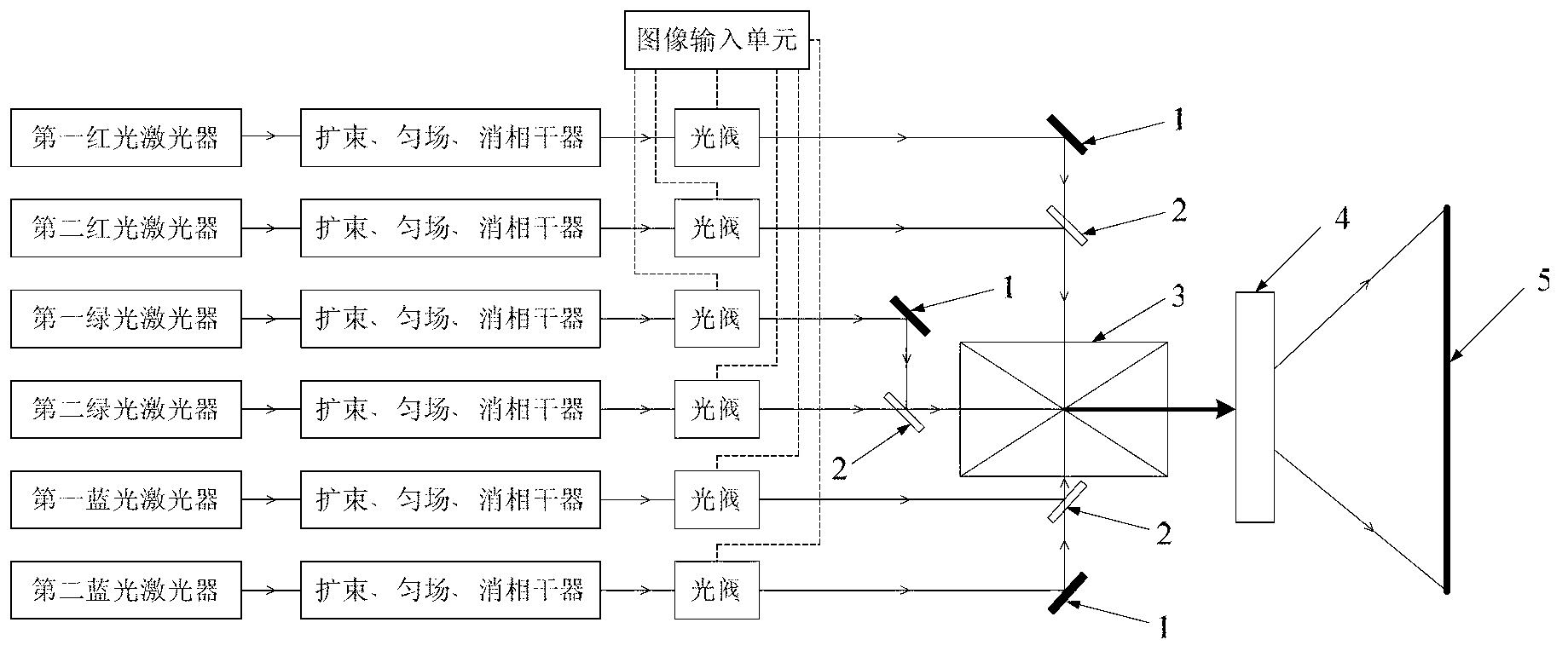
[0050] Such as figure 2 As shown, in this embodiment, the display device includes a laser light source, a beam expander, a shimming unit, a decoherence unit, an image signal modulation unit, an image synthesis unit, an image amplification unit, and a display unit.

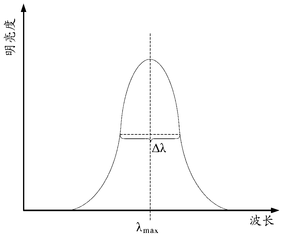
[0051] Wherein, the laser light source adopts two groups, and each group of laser light source includes three monochromatic lasers respectively, and is respectively a red light laser, a green light laser and a blue light laser, and one group in the two groups of laser light sources includes the first red light source light laser, the first green laser and the first blue laser, the other group includes the second red laser, the second green laser and the second blue laser, and two monochromatic lasers of the same color in the two groups of laser light sources The emitted laser light has different peak wavelengths, for example, the peak wavelengths or frequencies of the laser light emitted by the first red laser and...

Embodiment 2

[0067] The difference between this embodiment and embodiment 1 is:

[0068]The laser light source described in this embodiment adopts three groups, any two groups are used as light sources, and the remaining group is used as backup light sources. Of course, the 3D display device also includes beam expansion, shimming, decoherence units, light valves, and converging units corresponding to the backup light source, so that the laser light emitted by the backup light source is collimated and shimmed through beam expansion. After shaping and decoherence, the laser light is modulated by the light valve, and then converged to the same position in the color combining prism by the converging unit together with the laser light emitted by other laser light sources.

[0069] Other structures, materials and functions in this embodiment are the same as those in Embodiment 1, and will not be repeated here.

Embodiment 3

[0071] The difference between this embodiment and embodiment 1 is:

[0072] The 3D display device does not include beam expansion, shimming, and decoherence units, and the six laser beams emitted by the two groups of laser light sources are directly transmitted to the corresponding light valves.

[0073] Other structures, materials and functions in this embodiment are the same as those in Embodiment 1, and will not be repeated here.


PUM

PropertyMeasurementUnit
Wavelengthaaaaaaaaaa
Peak wavelengthaaaaaaaaaa

Abstract

The invention provides a 3D display device, which comprises a display light source, wherein the display light source is spectrally unmixed two or more groups of laser light sources; peak wavelengths of homochromatic lasers generated by each group of laser light sources in the two or more groups of laser light sources are different. Correspondingly, the invention further provides glasses matched with the 3D display device. The 3D display device has the advantages that the displayed picture has vivid colors, the resolution ratio is not lost, crosstalk is not easy to generate, and the angle of view is not influenced.

Description

technical field [0001] The invention belongs to the technical field of image display, and in particular relates to a 3D display device and glasses used in conjunction with it. Background technique [0002] 3D display technology has become a development trend in the display field. At present, 3D display technology is generally realized by using the principle of binocular parallax, that is, two parallax images (ie, left and right parallax images) are displayed on a two-dimensional display screen, and then a certain technology is used to make the viewer's left and right eyes respectively Only the left and right parallax images on the display can be seen. [0003] Existing 3D display technologies mainly include polarized light 3D display technology, shutter 3D display technology and color separation 3D display technology. Among them, polarized light 3D display technology generally adopts the method of dividing space, so half of the resolution will be lost, the effect of 3D dis...

Claims


Application Information

Patent Timeline
IPC IPC(8): G02B27/22H04N13/04
Inventor 晏斌陈维涛喻娟
Owner BOE TECH GRP CO LTD
Why Eureka
Try Eureka