Touch panel, touch display panel, and touch display device

A touch panel and display panel technology, which is applied in the fields of instruments, electrical digital data processing, and data processing input/output processes, etc., can solve the problems of inability to install electrostatic protection components, narrowing the border of the touch panel, etc., and achieve good static electricity. The effect of the protective effect

Active Publication Date: 2012-11-28
AU OPTRONICS CORP
View PDF5 Cites 44 Cited by
  • Summary
  • Abstract
  • Description
  • Claims
  • Application Information

AI Technical Summary

Problems solved by technology

[0004] However, since the guard ring will occupy a considerable area of ​​the bezel area, the manufacture of the guard ring will prevent the bezel of the touch panel from being further narrowed
On the other hand, if there is no protective ring, the narrow frame cannot be equipped with electrostatic protection components to eliminate static electricity

Method used


Image

  • Touch panel, touch display panel, and touch display device
  • Touch panel, touch display panel, and touch display device
  • Touch panel, touch display panel, and touch display device

Examples


Embodiment Construction

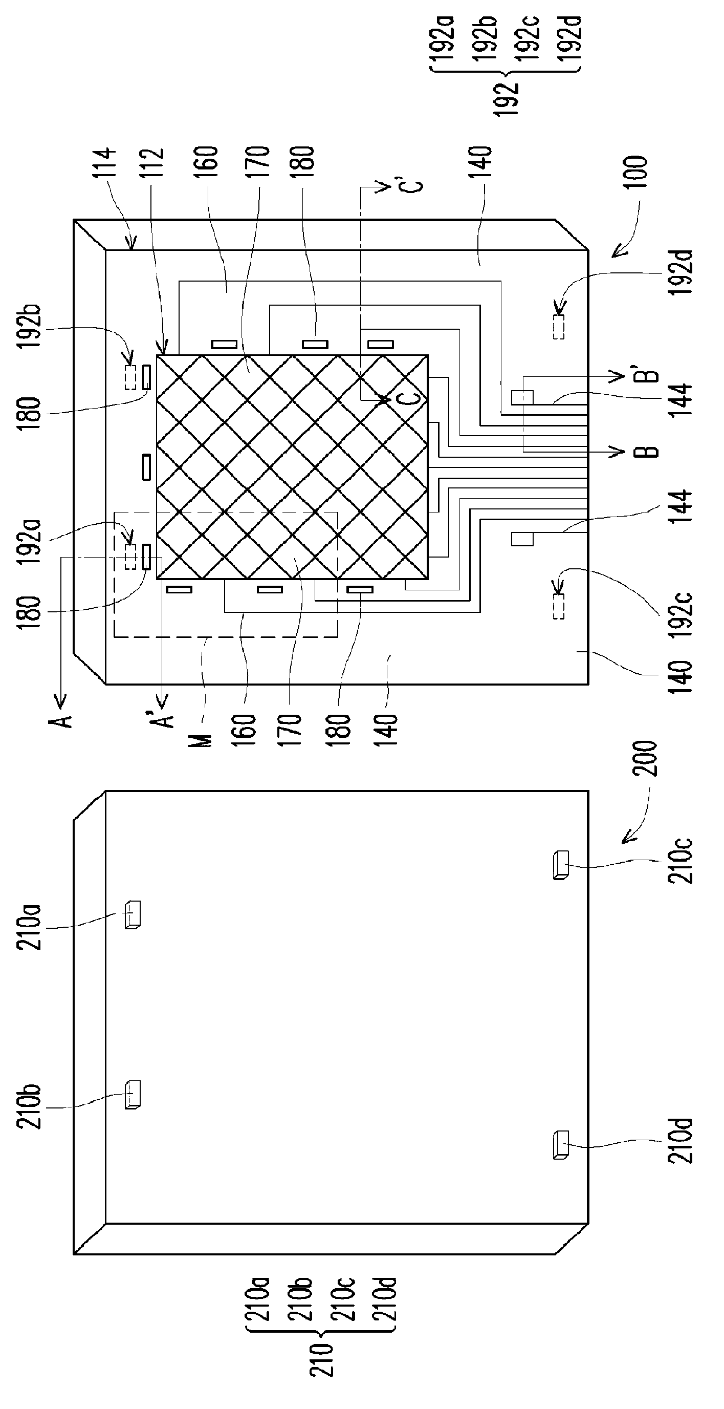
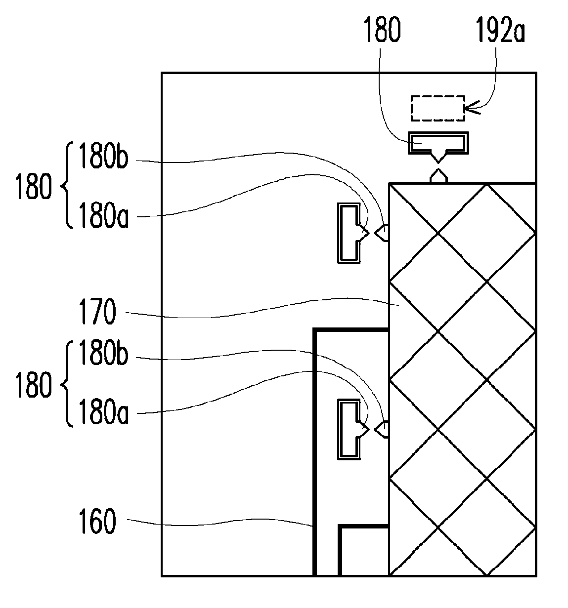
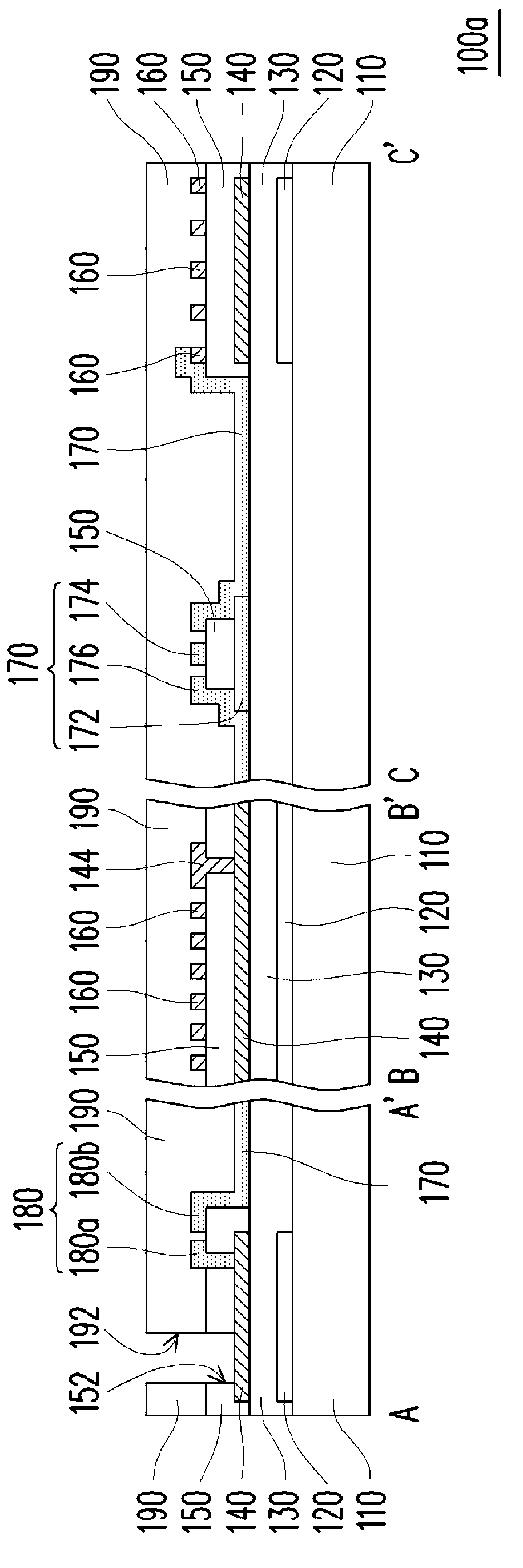
[0054] Figure 1A is a three-dimensional schematic view of the touch panel and the housing assembly according to the first embodiment of the present invention, wherein Figure 1A Partial film layers are omitted. Figure 1B forFigure 1A The enlarged schematic diagram of the local M. Figure 2A is a schematic cross-sectional view of the touch panel according to the first embodiment of the present invention, and Figure 2A respectively draw along Figure 1A Schematic cross-sectional views of the midlines A-A', B-B' and C-C'.

[0055] Please also refer to Figure 1A , Figure 1B as well as Figure 2A , the touch panel 100 a of this embodiment can be combined with the housing assembly 200 , and the housing assembly 200 has at least one conductive bump 210 . The touch panel 100a includes a substrate 110 , a frame pattern layer 120 , a touch sensing element 170 , a reflection protection electrode 140 , an ESD protection element 180 , a signal connection line 160 , an insulation la...


PUM


Abstract

A touch panel can be combined together with a case assembly, the case assembly is provided with at least one conductive projection. The touch panel comprises a substrate, a frame pattern layer, a touch sensing component, a reflecting protection electrode, an electrostatic protection component, a plurality of signal connecting lines, an insulating layer, and a covering layer; wherein, the frame pattern layer is arranged on the substrate at a peripheral region; the reflecting protection electrode is overlapped with the frame pattern layer; the electrostatic protection component is connected with the touch sensing component and the reflecting protection electrode, for transferring static electricity of the touch sensing component to the reflecting protection electrode; the signal connecting lines are overlapped with the frame pattern layer and electrically connected with the touch sensing component; the covering layer has at least one contact opening exposing a part of the reflecting protection electrode, for electrically connecting the reflecting protection electrode to the conductive projection of the case assembly through the contact opening.

Description

【Technical field】 [0001] The present invention relates to a touch panel, and in particular to a touch panel for a touch display device. 【Background technique】 [0002] In recent years, touch technology has been widely used in various multimedia electronic products, especially portable mobile products, such as mobile phones, e-books, and tablet computers. Using touch technology as an input means can effectively replace the existing keyboard or mouse input methods. In addition to convenience, touch input technology has become a very popular man-machine interface and multimedia interaction method due to its intuitive operation. [0003] Generally speaking, in the manufacturing process of the touch panel, a guard ring is formed on the peripheral area of ​​the touch panel, and the guard ring is arranged outside the signal connection lines. The guard ring is usually a grounded metal line with a wide line width, so the guard ring can effectively reduce the phenomenon that the noi...

Claims


Application Information

Patent Timeline
Patent Type & Authority Applications(China)
IPC IPC(8): G06F3/041
CPCG06F3/044G06F3/0443G06F3/0446
Inventor 林城兴郭威宏周诗博黄彦衡
Owner AU OPTRONICS CORP
Why Eureka
Try Eureka