Light control door lock convenient for managing user authority
A technology for managing users and door locks, applied to instruments, time registers, individual input/output registers, etc., can solve the problems of inconvenient management of users
- Summary
- Abstract
- Description
- Claims
- Application Information
AI Technical Summary
Problems solved by technology
Method used
Image

Examples
Embodiment 1
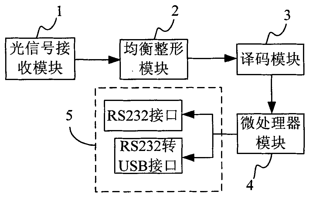
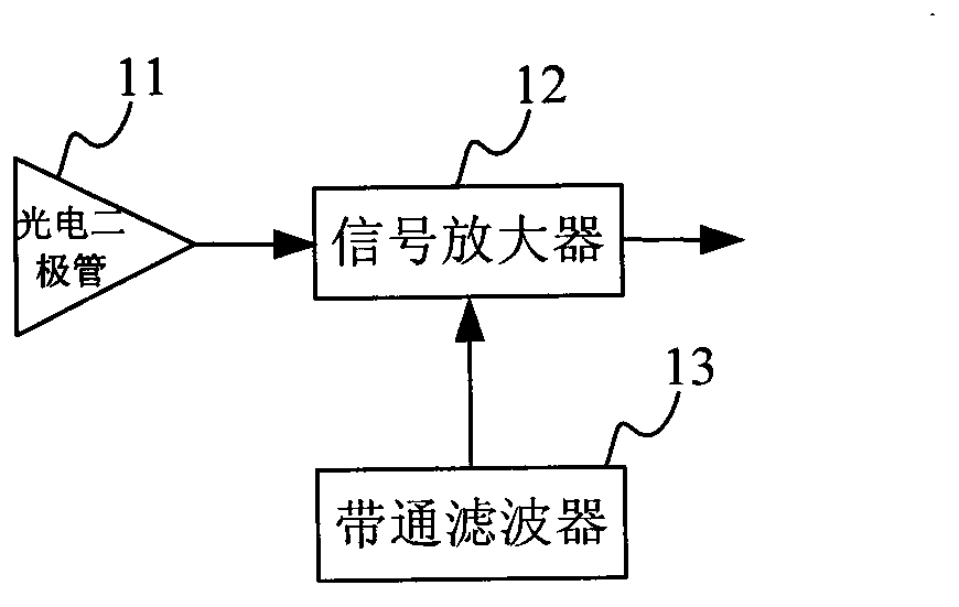
[0024] see figure 1 and figure 2 According to the present invention, the light-controlled door lock that is convenient for managing user rights includes an optical signal receiving module 1 , an equalization shaping module 2 , a decoding module 3 , a microprocessor module 4 and a protocol conversion module 5 . The optical signal receiving module 1 is used to convert the optical signal containing ID number information and password information emitted by the photon key into an electrical signal, and the code type of the optical signal emitted by the photon key is a CMI code. The optical signal receiving module 1 includes a photodiode 11 , a signal amplifier 12 and a bandpass filter 13 , and the photodiode 11 and the bandpass filter 13 are electrically connected to the signal amplifier 12 respectively. In this embodiment, the photodiode 11 is an avalanche photodiode, and the signal amplifier 12 is a transimpedance amplifier.
[0025] The avalanche photodiode is a p-n junction ...
Embodiment 2
[0033] see Figure 5 , this embodiment is similar to Embodiment 1, and the same thing is that they all include an optical signal receiving module 1, a microprocessor module 4 and a protocol conversion module 5; the difference is that in this embodiment, the optical Between the signal receiving module 1 and the microprocessor module 4 are a primary signal amplifier 6, a secondary signal amplifier 7 and a demodulator 8 electrically connected in sequence, and the primary signal amplifier 6 is used for optical signal receiving module 1 The output current signal is converted into a voltage signal, and the voltage signal is amplified and output; the secondary signal amplifier 7 is used to continue to amplify the signal output by the primary signal amplifier 6 until the microprocessor module 4 can Processed signal: the demodulator 8 is used to demodulate the ID signal transmitted from the secondary signal amplifier 7 according to the transmitted ID format, and transmit it to the proc...
PUM
 Abstract
Description
Claims
Application Information
 - R&D
- Intellectual Property
- Life Sciences
- Materials
- Tech Scout
- Unparalleled Data Quality
- Higher Quality Content
- 60% Fewer Hallucinations
Browse by: Latest US Patents, China's latest patents, Technical Efficacy Thesaurus, Application Domain, Technology Topic, Popular Technical Reports.
© 2025 PatSnap. All rights reserved.Legal|Privacy policy|Modern Slavery Act Transparency Statement|Sitemap|About US| Contact US: help@patsnap.com