Printed Yagi antenna of vibrator loading type balance microstrip line feed

A technology for balancing microstrip lines and Yagi antennas, applied in antennas, antenna grounding switch structural connection, electrical components, etc., can solve problems such as large size, achieve size reduction, reduce size, and facilitate operation and maintenance.

Inactive Publication Date: 2012-11-28
HARBIN INST OF TECH
View PDF2 Cites 34 Cited by
  • Summary
  • Abstract
  • Description
  • Claims
  • Application Information

AI Technical Summary

Problems solved by technology

[0003] In order to solve the problem that the size of the feeding structure of the existing printed Yagi antenna is ...

Method used


Image

  • Printed Yagi antenna of vibrator loading type balance microstrip line feed
  • Printed Yagi antenna of vibrator loading type balance microstrip line feed
  • Printed Yagi antenna of vibrator loading type balance microstrip line feed

Examples


specific Embodiment approach 1

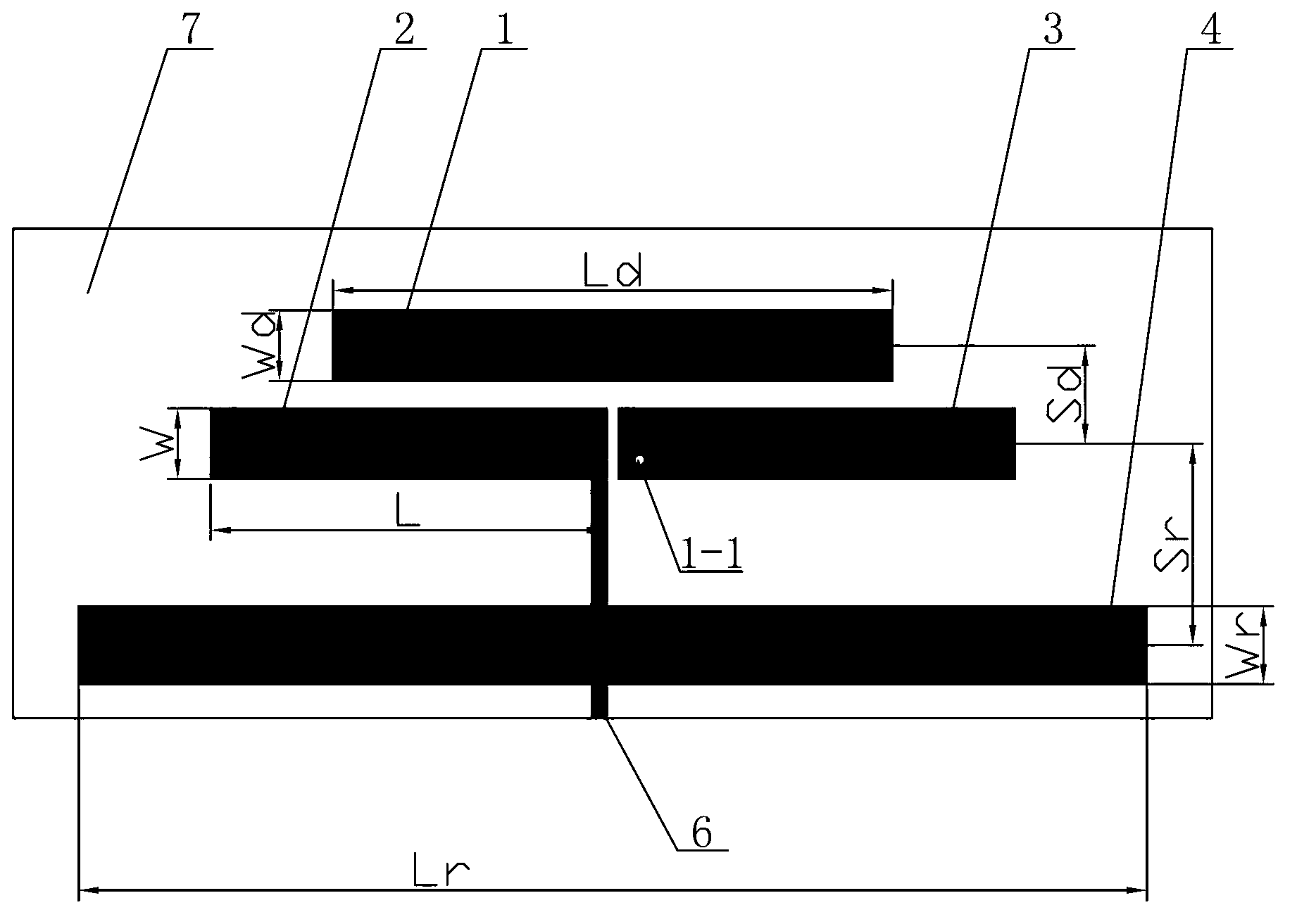
[0007] Specific implementation mode one: combine figure 1 with figure 2 Describe this embodiment, a printed-type Yagi antenna loaded with an oscillator in this embodiment and fed by a balanced microstrip line includes a dielectric board 7, and this embodiment also includes a director 1, a first symmetrical oscillator 2, a second symmetrical The vibrator 3, the reflector 4, the terminal feeder loading 5 and the feeding part 6, the director 1 and the reflector 4 are printed side by side on the front side of the dielectric plate 7 from top to bottom, and the first symmetrical vibrator 2 and the second symmetrical vibrator 3 is printed in a straight line between the director 1 and the reflector 4, the reflector 4 is connected to the feeding part 6 located in the middle of the lower edge of the dielectric plate 7, and the first symmetrical vibrator 2 is close to the side of the second symmetrical vibrator 3 The feeder is connected to the reflector 4 through the feeder, the termin...

specific Embodiment approach 2

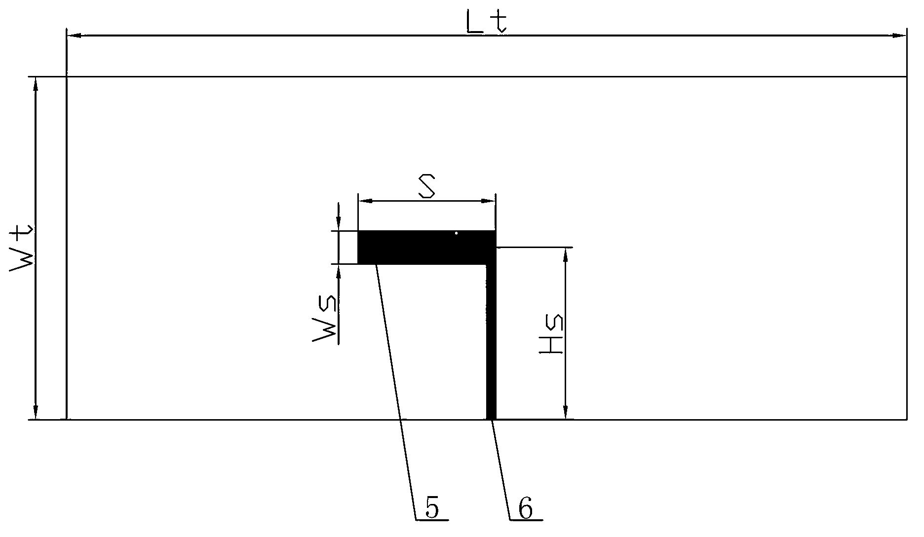
[0009] Specific implementation mode two: combination figure 1 with figure 2 Describe this embodiment, the length Ld of the director 1 of the printed Yagi antenna of the dipole-loaded balanced microstrip line feeding described in this embodiment is 42mm, the width Wd of the director 1 is 5.8mm, the first The length L of the symmetrical oscillator 2 is 31 mm, the width W of the first symmetrical oscillator 2 is 6.4 mm, the structural size of the second symmetrical oscillator 3 is the same as that of the first symmetrical oscillator 2, the length Lr of the reflector 4 is 89.3 mm, and the reflector 4 The width Wr of the terminal feeder is 6.4mm, the length S of the terminal feeder load 5 is 16.5mm, the width Ws of the terminal feeder 5 is 4mm, the length Lt of the dielectric plate 7 is 100mm, and the width Wt of the dielectric plate 7 is 38.5mm. Other components and connections are the same as those in the first embodiment.

specific Embodiment approach 3

[0010] Specific implementation mode three: combination figure 1 with figure 2 Describe this embodiment, the center distance Sd between the director 1 and the second symmetrical vibrator 3 of the printed Yagi antenna of the dipole-loaded balanced microstrip line feeding described in this embodiment is 5.8mm, and the second symmetrical The center distance Sr between the vibrator 3 and the reflector 4 is 8.7 mm, and the distance Hs between the center of the terminal feeder loading 5 and the lower edge of the dielectric plate 7 is 19.5 mm. Other components and connections are the same as those in the first embodiment.


PUM

PropertyMeasurementUnit
Lengthaaaaaaaaaa
Widthaaaaaaaaaa
Lengthaaaaaaaaaa

Abstract

The invention discloses a printed Yagi antenna of vibrator loading type balance microstrip line feed, relating to a printed Yagi antenna, in particular to a printed Yagi antenna of vibrator loading type balance microstrip line feed. The invention aims to solve the problem that the existing printed Yagi antenna feed structure has a very large size. In the invention, a first symmetric vibrator and a second symmetric vibrator are printed between a director and a reflector in a straight manner; the reflector is connected with a feed part in the middle of the lower edge of a dielectric slab; one side of the first symmetric vibrator close to the second symmetric vibrator is connected with the reflector through a feeder; a dead-end feeder load is printed on the back of the dielectric slab and connected with the feed part printed in the middle of the lower edge of the dielectric slab through a feeder; the second symmetric vibrator is connected with the feed through a metalized feed via hole by a balance microstrip line on the back of the dielectric slab; and the diameter of the metalized feed via hole is 1mm. The printed Yagi antenna disclosed by the invention is applied to the field of radio technology.

Description

technical field [0001] The invention relates to a printed Yagi antenna, in particular to a printed Yagi antenna loaded by an oscillator and fed by a balanced microstrip line. Background technique [0002] The Yagi antenna was invented by Yagi Hideji and Uda Taro of Tohoku University in Japan in 1928. Since it came out, it has been widely used in radio communication and radar systems due to its simple structure and high gain. The structure of this antenna is generally composed of an active oscillator (usually a half-wave oscillator), a reflector and several directors, and the typical structure is a cylindrical oscillator structure. With the deepening of the research on the antenna, there have been directional antennas with active oscillators in the form of folded oscillators, fan-shaped oscillators, and conical oscillators, and the reflectors have also appeared in the form of corner reflectors and parabolic reflectors. With the development of printed circuit technology, Qian...

Claims


Application Information

Patent Timeline
IPC IPC(8): H01Q1/38H01Q1/50H01Q13/08H01Q19/00H01Q19/10
Inventor 林澍荆丽雯田雨刘曦马欣茹徐扬董佳鑫
Owner HARBIN INST OF TECH
Why Eureka
Try Eureka