Hyperpolarisation device using photons with orbital angular momentum

A technology of orbital angular momentum and photons, applied in the application of optical pumps for analysis, double resonance for measurement, optics, etc.

Inactive Publication Date: 2012-11-28
KONINKLIJKE PHILIPS ELECTRONICS NV
View PDF1 Cites 4 Cited by
  • Summary
  • Abstract
  • Description
  • Claims
  • Application Information

AI Technical Summary

Problems solved by technology

Therefore, known magnetic resonance examination systems will only acquire magnetic resonance signals from a restricted region of the subject, which is limited by the minimum beam diameter

Method used


Image

  • Hyperpolarisation device using photons with orbital angular momentum
  • Hyperpolarisation device using photons with orbital angular momentum
  • Hyperpolarisation device using photons with orbital angular momentum

Examples


Embodiment Construction

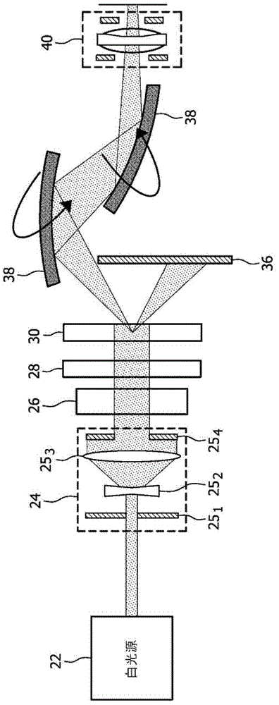
[0031] figure 1 An exemplary arrangement of the optical element of the present invention for imparting OAM to light is shown. It should be understood that any electromagnetic radiation can be imparted to OAM, not just visible light. The described embodiment uses visible light. It interacts with molecules of interest and has no damaging effect on living tissues. However, light / radiation above or below the visible spectrum is also thought of. The white light source 22 generates visible white light, which is sent to the beam expander 24. In particular, the white light source produces several simultaneous visible white light beams. Each of these several beams passes through subsequent optical components which will be explained next. The white light source incorporates source control to manage the simultaneous emission of several beams. This source control is part of the beam controller. In an alternative embodiment, if carefully chosen, the frequency and coherence of the ligh...


PUM


Abstract

A magnetic resonance examination system comprises an RF-system for inducing resonance in polarised dipoles and receiving magnetic resonance signals from an object to be examined and an photonic-based hyperpolarisation device. The an electromagnetic source for emitting photonic radiation: - a mode converter to impart orbital angular momentum to the electromagnetic radiation; a spatial filter to select from the mode converter a diffracted or refracted photonic beam endowed with orbital angular momentum for polarising the dipoles via transferred orbital angular momentum; - a beam controller to apply the photonic beam endowed with orbital angular momentum over an extended target zone.

Description

Technical field [0001] The invention relates to a magnetic resonance inspection system equipped with a photon-based hyperpolarization device. Background technique [0002] Such a magnetic resonance examination system is described in the international application PCT / IB2008 / 055444. Known magnetic resonance examination systems include optical-based hyperpolarization equipment. In particular, the hyperpolarization device generates an optical (e.g. light) beam that imparts orbital angular momentum. The orbital angular momentum (OAM) of the light beam is coupled with the (nucleon or molecule) dipole (or spin) to generate (nucleon or molecule) polarization (polarisation). This polarization is excited by RF radiation and a magnetic resonance signal is generated upon relaxation of the excitation. From these magnetic resonance signals, a magnetic resonance image is reconstructed. Because the polarization is generated by the orbital angular momentum of the light beam, either an externa...

Claims


Application Information

Patent Timeline
Patent Type & Authority Applications(China)
IPC IPC(8): G01N24/00G01R33/62
CPCG01R33/62G01N24/006G02B26/0816G02B5/10G01R33/282G02B27/0955
Inventor D・R・埃尔戈特L・R・阿尔布
Owner KONINKLIJKE PHILIPS ELECTRONICS NV
Why Eureka
Try Eureka