
Film forming device, film forming method, rotational frequency optimisation method, and storage medium

A technology of film forming device and starting position, applied in the direction of gaseous chemical plating, coating, electrical components, etc., can solve the problems of no hint, ambiguity, etc.

Active Publication Date: 2012-11-28
TOKYO ELECTRON LTD
View PDF13 Cites 6 Cited by
  • Summary
  • Abstract
  • Description
  • Claims
  • Application Information

AI Technical Summary

Problems solved by technology

In addition, in paragraph 0050 of Patent Document 6, it is disclosed that "It is preferable to fine-tune the rotation speed and the supply timing of the gas with respect to the rotation of the substrate so that the gas supply port does not come to the same position every time, adjust the rotation speed and the supply timing of the gas, thereby Each cycle is staggered by 45 degrees", but neither discloses nor hints how to adjust the rotation speed and gas supply timing in which relational expression. Therefore, in the production site of semiconductor devices where there are various combinations of these parameters, which Combining as non-synchronous is not clear and cannot be implemented by those skilled in the art

Method used


Image

  • Film forming device, film forming method, rotational frequency optimisation method, and storage medium
  • Film forming device, film forming method, rotational frequency optimisation method, and storage medium
  • Film forming device, film forming method, rotational frequency optimisation method, and storage medium

Examples


no. 1 Embodiment

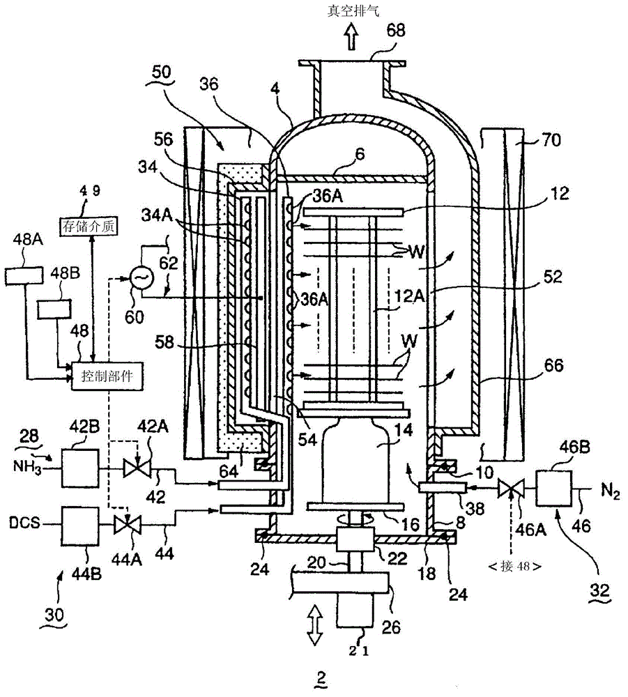
[0139] A case where ALD film formation is performed under the above-mentioned condition 2 for 30 cycles using the film formation apparatus 2 of the present invention will be described. First, the operating conditions of the device are input in advance. When data such as processing temperature, processing pressure, and gas flow rate contain the above-mentioned condition 2 and the division number K of the number that determines the supply start direction of the processing gas, as a processing recipe, the operator automatically connects to the processing of the control unit 48. The condition input section 48A inputs data. Alternatively, data may be transferred from a high-level host computer to the control unit 48 as a processing recipe. The control unit 48 is built in beforehand, and is used to determine the rotational speed satisfying the division number K specified by the program. Now, if the division number K specified by the process program is K=30, the control unit 48 is ...

no. 2 Embodiment

[0164] As a second example, when 30 cycles of ALD film formation are performed under the previous condition 2 using the film formation apparatus 2 of the present invention, ALD 1 is described by controlling the rotation speed at 1.9 rpm according to the specified operating conditions. cycle T to achieve the purpose of the invention in the same way as in the first embodiment.

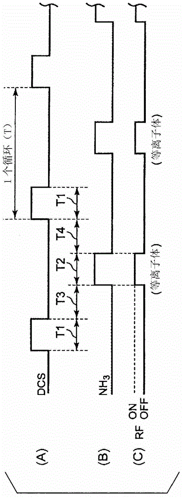
[0165]First, as in the first embodiment, the operating conditions of the device are input in advance. In this case, the control unit 48 can change the ALD without changing the supply sequence, supply time, and supply amount of the reaction gas under the operating conditions specified in advance by adjusting, for example, the time for vacuuming and purging the inside of the processing container. The period T of 1 cycle. Assuming that the period of one cycle of ALD is T1, when K=30 and the rotation speed of the substrate is N=1.9 (rpm), T1 is determined by the control unit 48 through the following calcula...

no. 3 Embodiment

[0222] Using the above relationship, try to find the ALD cycle time Tx when K=160, the resolution of the motor used is Q=200, and N is a number rounded off from the decimal point in the timing chart of condition 2.

[0223] R=K / G=160 / 200=4 / 5

[0224] According to the above formula (9), 4·α=5·β

[0225] 5·β is 5 times the step angle of the motor, so 5×1.8°=9°

[0226] At this time, if 4·α is the new moving angle, the moving angle is 4×2.25°=9°

[0227] Therefore, as long as the moving angle is 9° again, the new division number K' is 360 / 9=40

[0228] According to the previous formula (3), (n±1 / 40)=(1 / 60)·2×Tx

[0229] In this case, Table 1 describes the relationship between n and Tx.

[0230] Table 1

[0231]

[0232] The cycle time of ALD can be shortened from 95sec to 90.75sec by adopting n=3, + Tx=90.75.

[0233] It is also possible to change the cycle time of ALD from 95 sec to 119.24 sec by adopting Tx=119.25 where n=4, -.

[0234] Confirm the result, according...


PUM

PropertyMeasurementUnit
diameteraaaaaaaaaa

Abstract

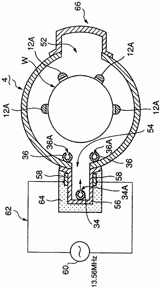
Disclosed is a film forming device which can inhibit a drop in the in-plane uniformity of the film thickness of the film which is formed. The disclosed film forming device (2) which forms a film on an object to be treated (W), is provided with: a treatment container (4); gas supply means (28, 30) comprising gas jetting openings (34A, 36A) which emit jets of gas; a holding means (12) which holds the object to be treated in the treatment container; a drive mechanism (21) which rotates the holding means relative to the gas jetting openings or periodically moves the holding means in relation to said gas jetting openings; and a control means (48) which, when a cycle, wherein a supply period when at least one kind of gas is supplied and a supply-stop period when the gas supply is stopped are carried out once, is repeated a plurality of times, with the number of repetitions of the cycle being P (P being a natural number not less than 2), controls a gas supply initiation position, as seen from the centre of the object to be treated, for P times of each cycle, in a manner such that the position sequentially moves one part at a time in the circumferential direction of the object to be treated, said parts being the circumference once round the object to be treated divided by an arbitrary division number (K) (K=P) of units.

Description

technical field [0001] The present invention relates to a film forming device, a film forming method, a method for optimizing a rotational speed, and a storage medium for forming a thin film formed by stacking reaction products by repeatedly supplying at least one reaction gas to the surface of a substrate such as a semiconductor wafer. Background technique [0002] As a film-forming method in a semiconductor manufacturing process, there is known a process in which a first reaction gas is adsorbed on the surface of a semiconductor wafer (hereinafter also simply referred to as "wafer") as a substrate in a vacuum atmosphere, and then The supplied gas is switched to the second reaction gas, and one or more atomic layers and molecular layers are formed by the reaction of the two gases, and this cycle is repeated multiple times to stack the above-mentioned layers and form a film on the substrate. This process is called, for example, ALD (Atomic Layer Deposition) and MLD (Molecula...

Claims


Application Information

Patent Timeline
Patent Type & Authority Applications(China)
IPC IPC(8): H01L21/31C23C16/455
CPCC23C16/45546C23C16/45525C23C16/515C23C16/507C23C16/45578C23C16/345C23C16/4584C23C16/52
Inventor 伊藤章三
Owner TOKYO ELECTRON LTD
Learn More