Roller C cleaning device and method for coating machine

A technology for cleaning devices and cleaning methods, applied in cleaning methods and appliances, cleaning methods using tools, cleaning methods using liquids, etc., can solve problems affecting battery performance, particle scratches, and uneven thickness of thin slurry, etc. Achieve the effect of improving the quality of the pole piece, improving the uniformity, and solving the particle scratches

Inactive Publication Date: 2012-12-05
TIANJIN LISHEN BATTERY
View PDF8 Cites 15 Cited by
  • Summary
  • Abstract
  • Description
  • Claims
  • Application Information

AI Technical Summary

Problems solved by technology

However, due to the wear of the scraper and the C roller, the scraper may not be able to completely scrape off all the slurry on the surface of the C roller, and there is still a thin layer of slurry on the surface of the C roller after passing the scraper. This thin layer of slurry has a great influence on the quality of the electrode. : 1) The thin layer of slurry on the surface of the C roller is very easy to contact with the air to absorb water. When passing through the diaphragm, part of the slurry gathers at the bottom of the diaphragm and is brought into the surface of the pole piece with the rotation of the C roller, forming particle scratches; 2 ) Due to the uneven thickness of the thin slurry on the surface of the C roller, it is also easy to cause poor coating effect; 3) After the thin slurry on the surface of the C roller absorbs water, it is coated into a pole piece, which may affect the final battery performance

Method used


Image

  • Roller C cleaning device and method for coating machine
  • Roller C cleaning device and method for coating machine

Examples


Embodiment Construction

[0017] In order to enable those skilled in the art to better understand the technical solutions of the present invention, the present invention will be further described in detail below in conjunction with the accompanying drawings and embodiments.

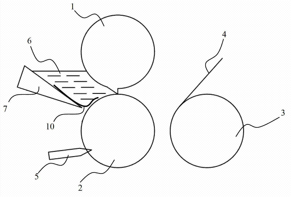
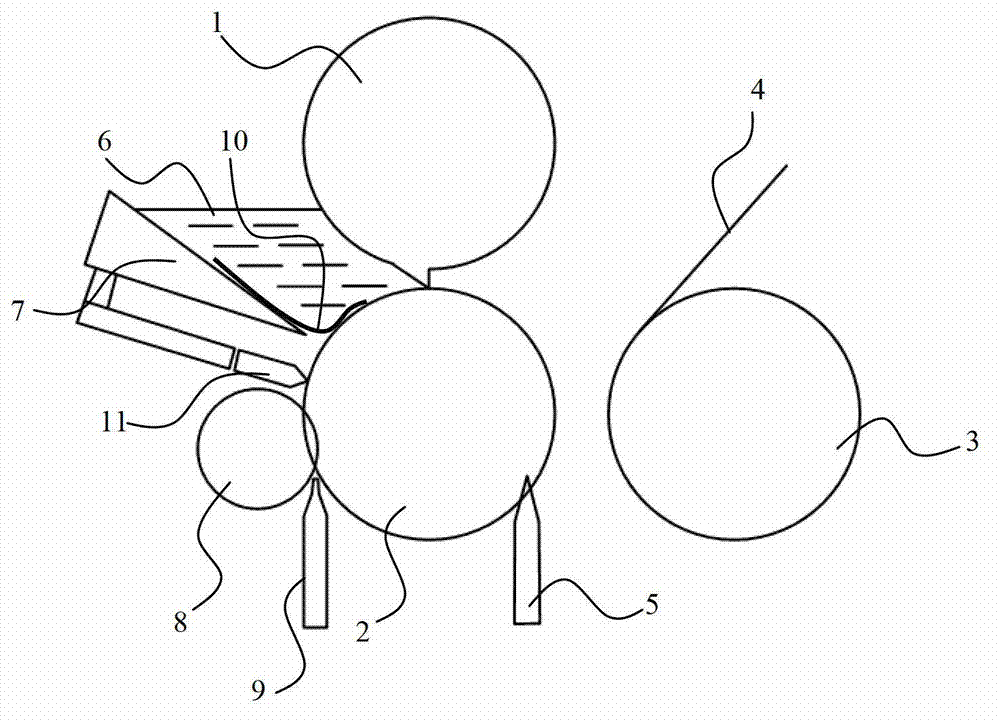
[0018] Such as figure 2 As shown, the coating machine adopting the structure of the present invention includes a comma roller 1 placed vertically and horizontally, a discharge roller 2 and a foil conveying roller 3, the discharge roller 2 is located directly below the comma roller 1, The foil conveying roller 3 is located on the right side of the discharge roller 2, and the outer surface of the foil conveying roller 3 is wound with a battery pole sheet foil 4; the lower right side of the discharge roller 2 is fixedly installed A first scraper 5, a baffle 7 is arranged on the left side of the comma roller 1 and the discharge roller 2, and a feeding groove 6 is formed between the outer surface of the discharge roller 2 and the baff...


PUM


Abstract

The invention discloses a roller C cleaning device for a coating machine. The roller C cleaning device comprises a first scraping knife fixedly arranged below the right side of a material discharging roller and further comprises a brush roller, which is positioned between the first scraping knife and a baffle and arranged parallel to an axial direction of the material discharging roller, wherein a washing liquid spray nozzle is arranged below the brush roller; and a second scraping knife in contact with the external surface of the material discharging roller is arranged between the brush roller and the baffle. A material discharging roller cleaning method of the coating machine comprises the following steps: 1) scraping a paste on the surface of the material discharging roller by the first scraping knife; 2) spraying a washing liquid to the material discharging roller by the washing liquid spray nozzle; and rotating the brush roller so as to wash the surface of the material discharging roller; and 3) wiping the surface of the material discharging roller by the second scraping knife so as to remove the paste and the washing liquid remaining on the surface of the material discharging roller. According to the invention, a problem that the paste is gathered at the bottom of a diaphragm can be solved, so that particle scratch problems generated due to material accumulation at the bottom of the diaphragm is completely solved and the quality of a pole piece is improved.

Description

technical field [0001] The invention relates to a lithium-ion battery production process, in particular to a coating machine C-roller cleaning device and method. Background technique [0002] Lithium-ion batteries have the advantages of high voltage, high specific energy, many cycle times, and long storage time. They are not only widely used in portable electronic devices such as mobile phones, digital cameras and laptop computers, but also widely used in electric vehicles, electric In terms of large and medium-sized electric equipment such as bicycles and electric tools, the requirements for lithium-ion batteries are getting higher and higher. The requirements for electrodes, which are the core components of lithium-ion batteries, are also getting higher and higher, such as: the coating amount of electrodes, the appearance of pole pieces, etc. [0003] Such as figure 1 As shown, the existing coating machine C roller cleaning device includes a comma type roller 1 placed ve...

Claims


Application Information

Patent Timeline
Patent Type & Authority Applications(China)
IPC IPC(8): B08B7/04B08B1/02B08B3/02B05C21/00
Inventor 付挺滕彦梅杨巍黄玉香
Owner TIANJIN LISHEN BATTERY
Why Eureka
Try Eureka