Device and method for hydraulic forming of cavity part with complex curved surface

A complex curved surface and hydroforming technology, which is applied in the field of hydroforming devices for complex curved surface cavity parts, can solve problems such as wall thickness reduction, parts that are difficult to form, and slabs that are difficult to flow into the mold cavity.

Inactive Publication Date: 2012-12-05
HARBIN INST OF TECH
View PDF5 Cites 8 Cited by
  • Summary
  • Abstract
  • Description
  • Claims
  • Application Information

AI Technical Summary

Problems solved by technology

[0004] The purpose of the present invention is to solve the problems of large welding deformation and high welding residual stress in the existing stamping and deep drawing forming technology for complex curved parts, and the existence of double plate hydroforming technology in the initial stage of forming, which requires a large mold clamping The double slabs are pressed hard to ensure the liquid seal of the liquid filling port. When forming complex curved cavity parts, it is difficult for the slabs at both ends of the cavity to flow into the mold cavity. The large bulging deformation makes the wall thickness thinner, and the parts Difficult to form, and then provide a complex curved surface cavity parts hydroforming device and method

Method used


Image

  • Device and method for hydraulic forming of cavity part with complex curved surface
  • Device and method for hydraulic forming of cavity part with complex curved surface
  • Device and method for hydraulic forming of cavity part with complex curved surface

Examples


specific Embodiment approach 1

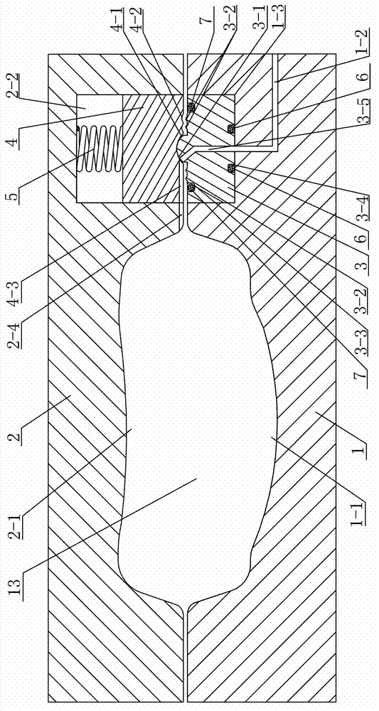
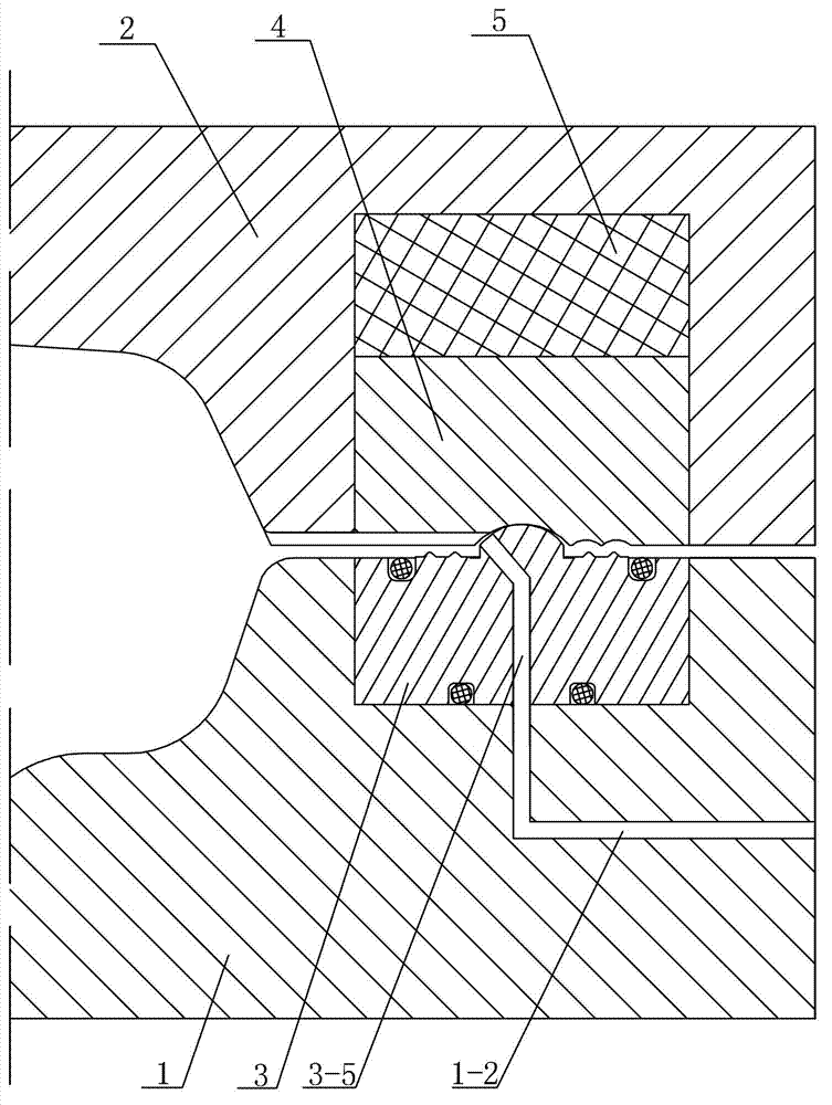
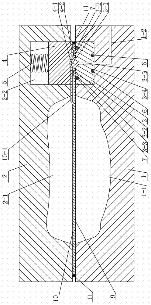
[0022] Specific implementation mode one: combine Figure 1-Figure 10This embodiment is described. The hydroforming device for complex curved cavity parts in this embodiment includes an upper die 2 and a lower die 1. The device also includes a lower liquid-filled insert 3, an upper liquid-filled insert 4, an elastic member 5, a second A sealing ring 6 and a second sealing ring 7, the lower end surface of the upper mold 2 has an upper cavity 2-1, the upper end surface of the lower mold 1 has a lower cavity 1-1, and the upper mold 2 and the lower mold 1 are completely closed The upper cavity 2-1 and the lower cavity 1-1 form the cavity 13 of the part to be formed, and an upper groove 2-2 is processed on the lower end surface of the upper mold 2 adjacent to the upper cavity 2-1, A lower groove 1-3 is processed on the upper end surface of the lower mold 1 at the position directly opposite to the upper groove 2-2, and the upper groove 2-2 is sequentially provided with an elastic mem...

specific Embodiment approach 2

[0023] Specific implementation mode two: combination figure 1 The present embodiment will be described. The elastic member 5 in the present embodiment is a spring. In this way, after the upper mold and the lower mold are closed, the spring can provide a pressing force between the upper liquid-filled insert and the lower liquid-filled insert, without being affected by the clamping force of the upper mold and the lower mold, and the liquid seal can be independent Control to meet the design requirements and forming needs. Others are the same as in the first embodiment.

specific Embodiment approach 3

[0024] Specific implementation mode three: combination figure 2 The present embodiment will be described. The elastic member 5 in the present embodiment is an elastic member made of polyurethane. In this way, after the upper mold and the lower mold are closed, the polyurethane can provide a pressing force between the upper liquid-filled insert and the lower liquid-filled insert without being affected by the clamping force of the upper mold and the lower mold, and the liquid seal can be independently Control to meet the design requirements and forming needs. Others are the same as in the first embodiment.


PUM


Abstract

The invention discloses a device and a method for hydraulic forming of a cavity part with a complex curved surface, and relates to a device and a method for forming metal plates. The device and the method solve the problem of large welding deformation and welding residual stress in the prior art for stamping and deep drawing of parts with complex curved surfaces and also solve problems that in the initial forming stage, double plate blanks need to be pressed by high mold clamping force to guarantee sealing of liquid at a liquid charging opening, so that the plate blanks at two ends of a cavity are difficult to flow into the cavity of a mold when a cavity part with a complex curved surface is formed, the wall thickness of the part is reduced due to high expansion deformation, and the part is difficult to form by the existing double-plate hydraulic forming technology. The device comprises an upper mold, a lower mold, a lower liquid charge insert, an upper liquid charge insert, an elastic component, a first sealing ring and a second sealing ring, the elastic component and the upper liquid charge insert are sequentially arranged in an upper groove from top to bottom, the lower liquid charge insert is arranged in a lower groove, and the second sealing ring is mounted in a second sealing groove. The device and the method are used for forming of the cavity part with the complex curved surface.

Description

technical field [0001] The invention relates to a metal plate forming device and method, in particular to a hydroforming device and method for complex curved cavity parts. Background technique [0002] Cavity parts with thin-walled and complex curved surfaces are a typical type of shell structural parts. The main difficulty in forming is that the shell that forms the cavity is a thin-walled and complex curved surface, and the cross-sectional size of the cavity varies greatly. For parts with small changes in cross-sectional size, pipe diameter expansion or reduction (such as pipe hydroforming, electromagnetic forming) and other forming methods are usually used. For parts with large cross-section changes, the method of relying on pipe diameter expansion is limited by the maximum expansion rate of the pipe, which may easily lead to local extreme thinning or even rupture of the pipe; similarly, the method of pipe shrinkage forming may easily lead to local material instability D...

Claims


Application Information

Patent Timeline
IPC IPC(8): B21D26/021B21D26/031B21D26/027
Inventor 刘伟刘钢苑世剑
Owner HARBIN INST OF TECH
Why Eureka
Try Eureka