

Magnetic detection apparatus
A magnetic detection device and the technology of the detection device are applied in the directions of measurement devices, electric devices, and electric/magnetic devices to transmit sensing components, which can solve problems such as the deterioration of the reliability of the output voltage of the detector.
- Summary
- Abstract
- Description
- Claims
- Application Information
AI Technical Summary
Problems solved by technology
Method used
Image

Examples
no. 1 example
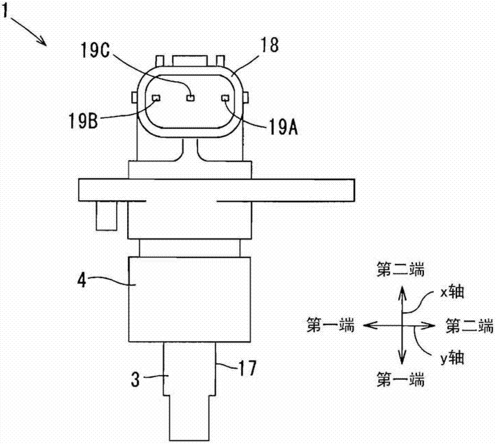
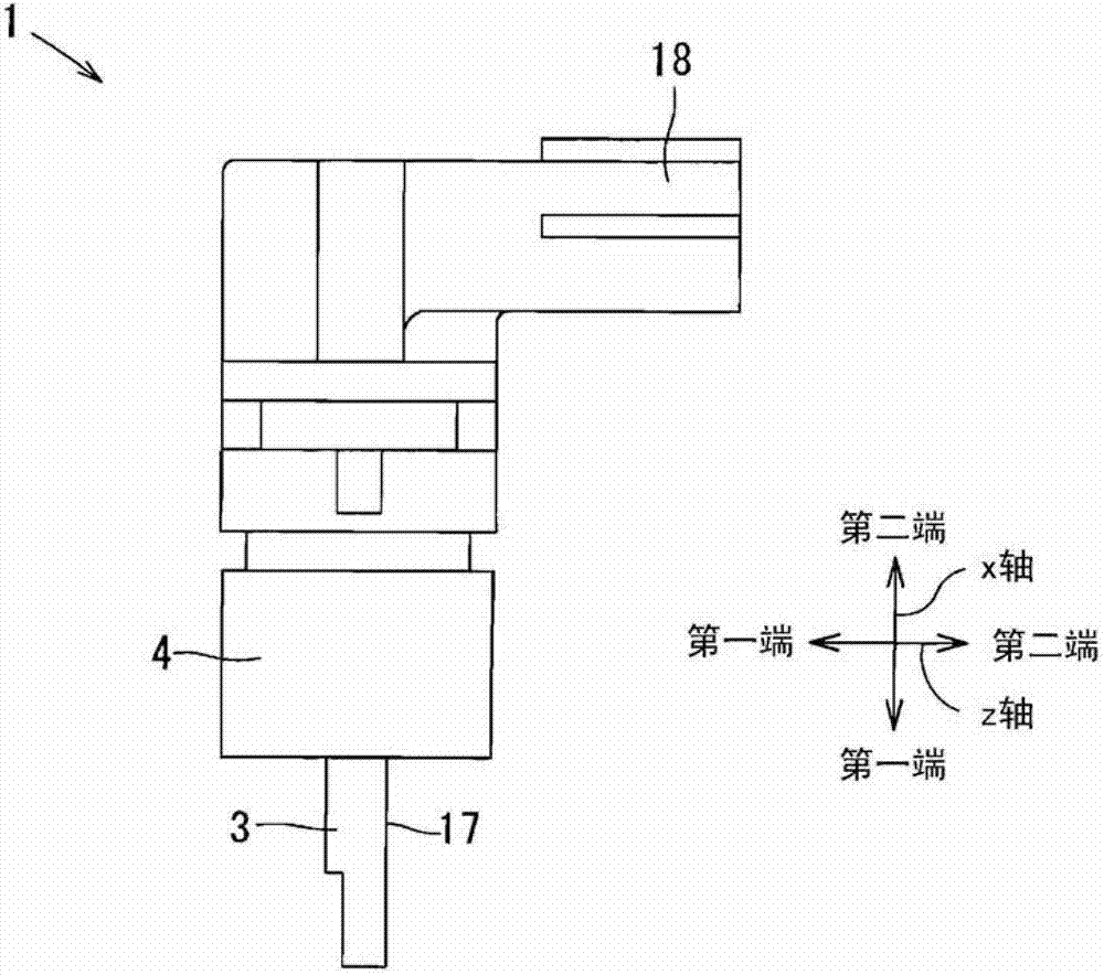
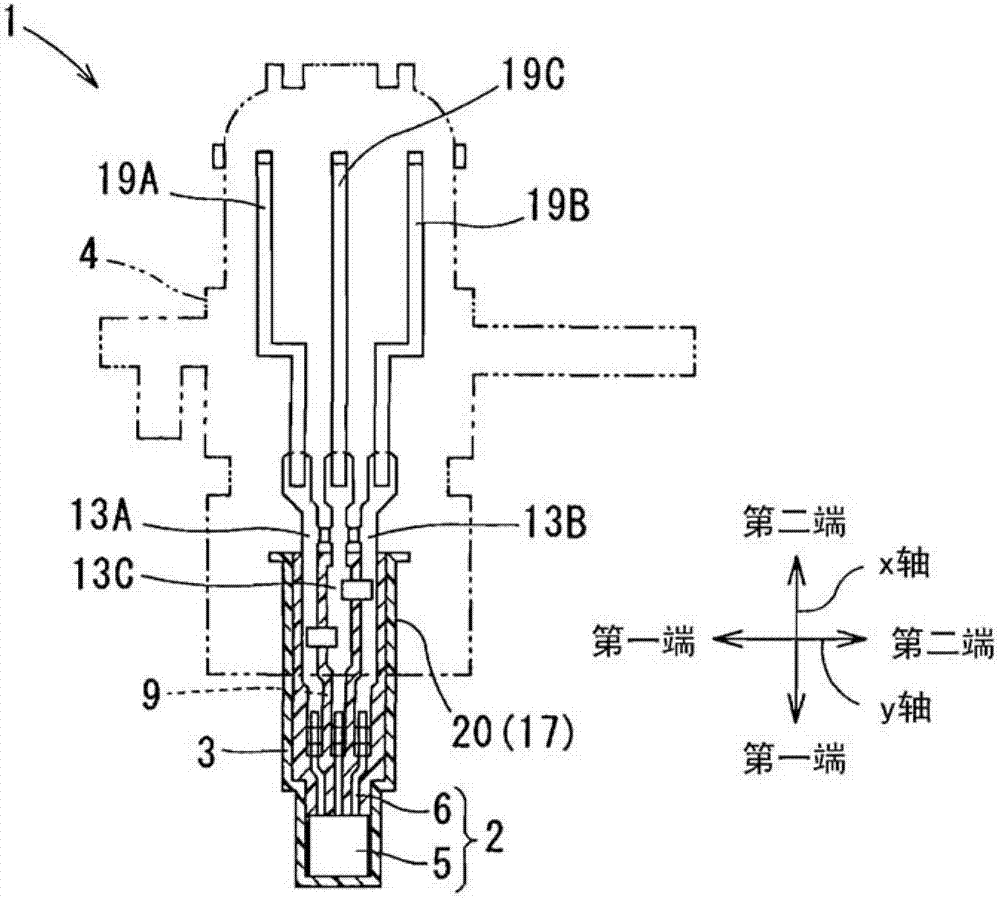
[0035] will refer to Figure 1A to Figure 3C A magnetic detection device 1 (hereinafter referred to as a detection device) according to a first embodiment will be described. For example, the detection device 1 includes: a magnetoelectric transducer (not shown) such as a Hall element; and a magnetic flux generator (not shown) such as a permanent magnet. When the flux generator is relatively rotated or moved about the magnetoelectric transducer to have a linear displacement relative to the magnetoelectric transducer, the magnetic field generated by the flux generator is changing. The detection device 1 detects a rotation angle or a linear displacement by combining a magnetic flux generator with a magnetoelectric transducer. That is, the detecting device detects a magnetic flux corresponding to a rotation angle or a linear displacement of the magnetic flux generator using the function of the magnetoelectric transducer, and generates a voltage corresponding to the detected magnet...
no. 2 example
[0062] will refer to Figure 4A to Figure 4D A detection device 1 according to a second embodiment will be described. In the detection device 1 according to the second embodiment, the opening portion 10 of the housing 3 is covered with the cover 22 . The cover 22 may be composed of, for example, a resin material similar to that of the housing 3 . The cover 22 has three through holes 23 corresponding to the extension terminals 13A to 13C. The extension terminals 13A to 13C penetrate through the respective through holes 23 , respectively. Furthermore, the extension terminal 13C has a stopper 24 to engage with the cover 22 when the extension terminals 13A to 13C penetrate the through hole 23 .
[0063] After the cover 22 is engaged with the extension terminal 13C by the stopper 24 , the cover 22 is integrated with the housing 3 by heat caulking to cover the opening 10 of the housing 3 . The housing 3 has a thermal caulking portion 25 at the second end side of the protrusion 1...
no. 3 example
[0065] will refer to Figure 5A and Figure 5B A detection device 1 according to a third embodiment will be described. The detection device 1 according to the third embodiment comprises a subassembly 27 comprising an insertion part 26 . The insertion part 26 includes the IC device 2 other than the IC package 5, the extension terminals 13A to 13C, and the capacitor 14, which are integrally molded by injection molding. The sub-assembly 27 is housed in the housing space 9 of the housing 3 , and then, the resin molded portion 4 is formed on a first portion of the outer surface 17 of the housing 3 .
[0066] With the above configuration, the positions of the extension terminals 13A to 13C and the position of the capacitor 14 are preliminarily defined and secured in the sub-assembly 27 . Then, the sub-assembly 27 is housed in the case 3 so that the IC package 5 is in contact with the sub-contact areas L0 to L4. Then, the resin molded portion 4 is formed on the first portion of t...
PUM
 Abstract
Description
Claims
Application Information