Phased array ultrasonic testing method based on improved dynamic depth focusing

A technology of dynamic depth focusing and ultrasonic detection, which is applied in the direction of using sound wave/ultrasonic wave/infrasonic wave to analyze solids and process detection response signals, etc. It can solve the distortion of phased array ultrasonic synthesis signal and affect the spatial resolution and Problems such as contrast, sound beam focusing and sound beam synthesis are difficult to achieve the effects of reducing hardware system errors, improving phased array ultrasonic imaging quality, and improving detection resolution

Inactive Publication Date: 2012-12-05
BEIHANG UNIV
View PDF0 Cites 48 Cited by
  • Summary
  • Abstract
  • Description
  • Claims
  • Application Information

AI Technical Summary

Problems solved by technology

[0005] During phased array ultrasonic testing, due to the deviation between the actual sound velocity of the tested material and the assumed sound velocity, or the presence of coarse grains, anisotropy, and non-uniformity in the tested material, the non-uniformity of the sound beam when the ultrasonic signal propagates will cause It causes the distortion of the phased array ultrasonic synthesis signal during the ultrasonic signal propagation process, which leads to the difficulty of beam focusing and beam synthesis during defect detection, which seriously affects the spatial resolution and contrast of phased array ultrasonic imaging

Method used


Image

  • Phased array ultrasonic testing method based on improved dynamic depth focusing
  • Phased array ultrasonic testing method based on improved dynamic depth focusing
  • Phased array ultrasonic testing method based on improved dynamic depth focusing

Examples


Embodiment

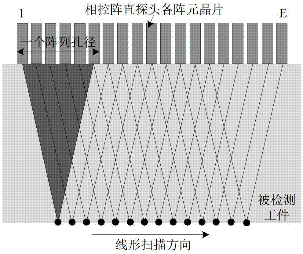
[0042] Example: This embodiment proposes a phased array ultrasonic detection method based on improved dynamic depth focusing, which includes the following steps:

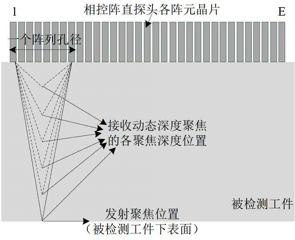
[0043] Step 1. Take a phased array one-dimensional linear straight probe containing E (32) array element chips as an example, and use the phased array linear electronic scanning method to transmit ultrasonic waves. First, take No. 1~E / 4 (1 ~No.8) array elements, these E / 4 array elements form the first array aperture, and calculate the delay time of each array element in the array aperture, so that the ultrasonic beam emitted by each array element is vertically focused and incident on the detected workpiece lower surface. Then, select No. 2~(E / 4+1) (No. 2~9), No. 3~(E / 4+2) (No. 3~10), No. 4~(E / 4+2) in the phased array straight probe respectively 4+3) (No. 4~11)...(3E / 4+1)~E (No. 25~32) array elements form different array apertures, then the probes of E array element chips contain a total of 3E / 4+ 1 (25) array ape...


PUM


Abstract

The invention belongs to the technical field of non-destructive testing and particularly discloses a phased array ultrasonic testing method based on improved dynamic depth focusing. The method comprises the following five steps of: performing phased array ultrasonic transmission and reception, discriminating a defect, calculating delay time, post-processing echo signals and reconstructing a B type drawing. The ultrasonic echo signals are accurately focused to the position of the defect, so that the problem that the defect is difficult to identify when the signal-to-noise ratio of a reflection echo signal of the defect is too low can be solved; by the method, the problem that the deviation exists between an ideal focus and an actual focus because a material of a tested workpiece is nonuniform can be effectively solved, and the testing resolution of phased array ultrasonic testing of layered media and anisotropic media can be effectively improved; and by the method, the problems that ultrasonic imaging results are fuzzy and distorted due to errors of hardware systems such as phased array flaw detectors can also be solved, and the quality of phased array ultrasonic imaging can also be improved.

Description

technical field [0001] The invention belongs to the technical field of nondestructive testing, and in particular relates to a phased array ultrasonic testing method based on improved dynamic depth focusing. Background technique [0002] Nondestructive testing (nondestructive testing), referred to as NDT, is based on the premise of not damaging the adaptability of the object to be tested, and uses a variety of physical principles and chemical phenomena to carry out effective inspection and testing of various engineering materials, parts, and structural parts. Evaluate their continuity, integrity, safety reliability and certain physical properties. The five conventional non-destructive testing methods mainly include radiographic testing, ultrasonic testing, penetrant testing, magnetic particle testing, and eddy current testing. [0003] Ultrasonic testing (UT) is to use the probe to stimulate the ultrasonic wave to be transmitted into the workpiece to be inspected after being...

Claims


Application Information

Patent Timeline
Patent Type & Authority Applications(China)
IPC IPC(8): G01N29/07G01N29/50
Inventor 周正干徐娜
Owner BEIHANG UNIV
Why Eureka
Try Eureka