

Device for fixing drainage tube
A technology of fixing device and drainage tube, applied in catheters and other directions, can solve the problems of inability to effectively observe and perform wound care, increase uncertain risks, unpredictable or untreated infection, etc., achieve definite and visible effects, improve application safety, The effect of large deformation rate
- Summary
- Abstract
- Description
- Claims
- Application Information
AI Technical Summary
Problems solved by technology
Method used
Image

Examples
Embodiment 1
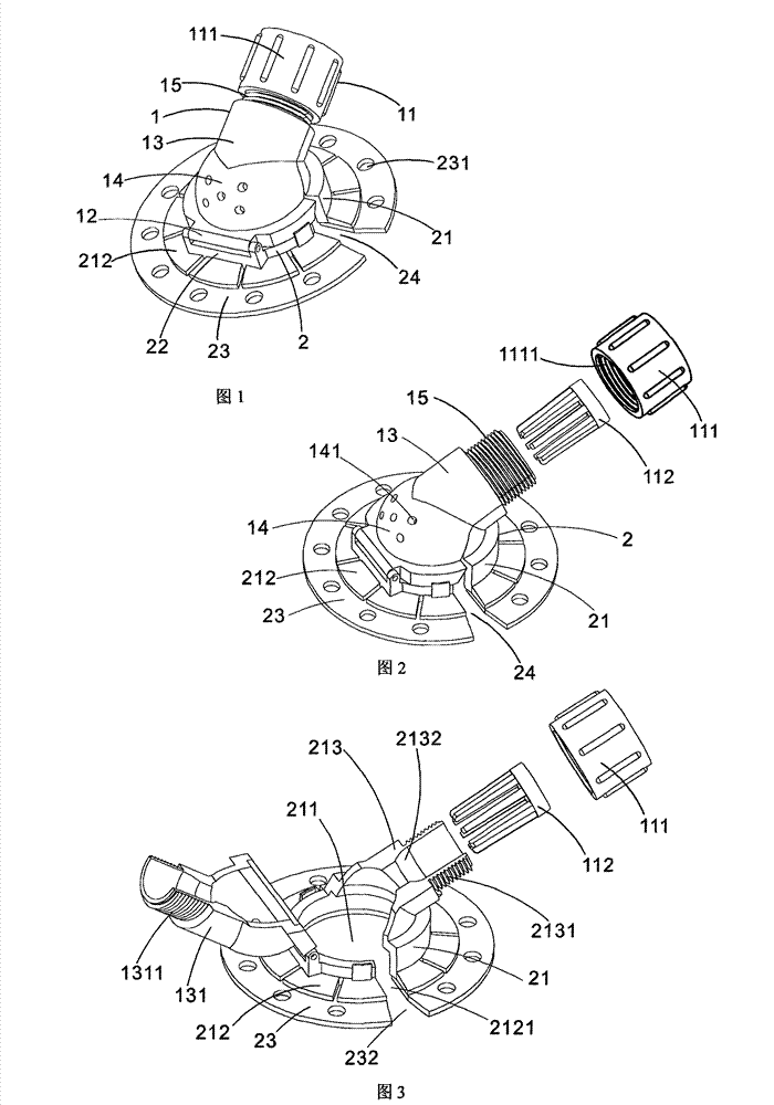
[0031] figure 1 , figure 2 and image 3 The drainage tube fixing device shown is composed of a drainage tube fixing component 1 and a body surface fixing component 2. The drainage tube fixing component 1 includes a holder 11, an upper connecting button 12 and a hollow tube 13. One end is connected to the holder 11, and the other end is connected to the upper connection buckle 12. The body surface fixing assembly 2 includes a base 21, a base hole 211, a lower connection buckle 22 and an adhesive layer 23, and the base hole 211 can accommodate Place a dressing that matches the shape of its opening, the holder 11 is provided with a tightening ring 111 and a tube locking grid 112, and the inner cavity lower end of the hollow tube 13 is provided with an inner tube for tightening and shrinking the tube locking grid 112 Cone, the inner wall of the tightening ring 111 is provided with internal threads 1111, the locking tube grid 112 is set in the inner cavity of the tightening ring...
Embodiment 2
[0037] Such as Figure 4 Shown is another embodiment of the present invention.
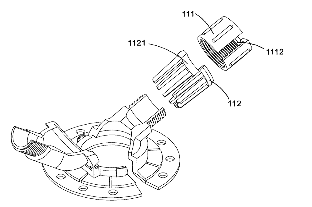
[0038] The difference between this solution and Embodiment 1 is that the tightening ring 111 is provided with a tightening ring nozzle 1112 with an arc length ≤ 1 / 3 of the circumference of the tightening ring 111, and the arc length is preferably ≤ 1 / 4 of the tightening ring 111 circumference; another difference is that the lock pipe grid 112 is made of elastic semi-rigid material, and is disconnected at the connection between any two grid bars to form a lock pipe grid placement nozzle 1121. In addition, it is the same as that of the embodiment 1 is exactly the same.
[0039] When in use, break apart the tube lock grid 1121, make the lock tube grid 112 cover the drainage tube and let it bounce back into a complete circular lock tube grid 112, and then press the drainage tube from the tightening ring tube port 1112 Enter the tightening ring 111, and rotate the tightening ring 111 to fix the drain...
Embodiment 3
[0041] Such as Figure 5 Shown is another embodiment of the present invention.
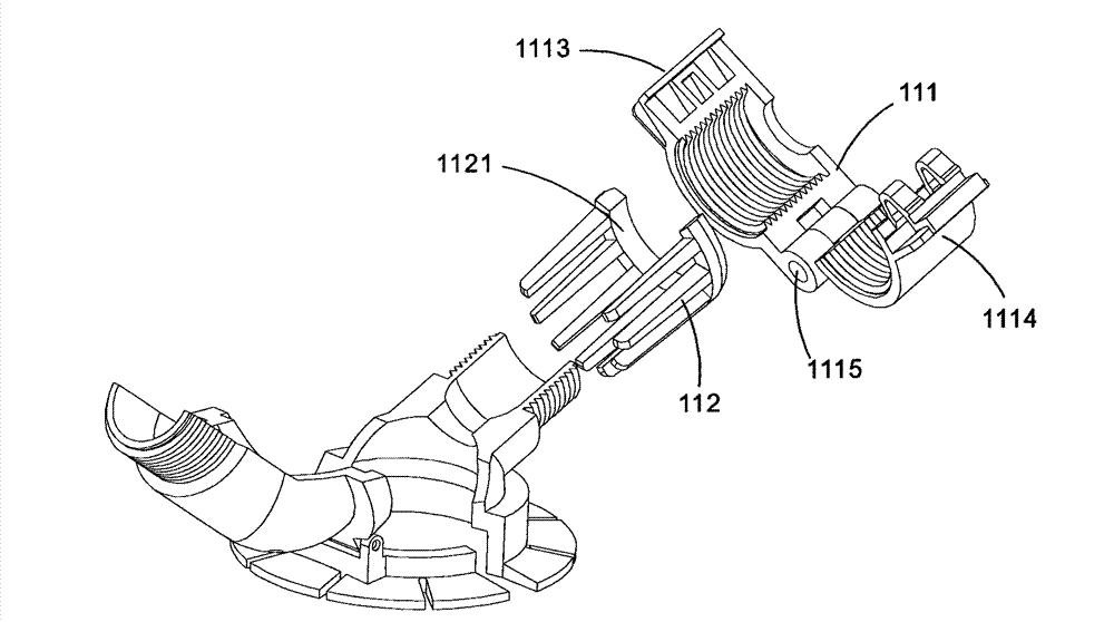
[0042] The difference between this scheme and Embodiment 2 is that the tightening ring 111 is composed of a left half ring 1113, a right half ring 1114 and a bolt 1115, wherein the bolt 1115 passes through the bottom ends of the left half ring 1113 and the right half ring 1114 to make it Connected in a hinged manner, the upper ends of the left half ring 1113 and the right half ring 1114 are provided with snap-on or loose buckles, and when the upper ends of the two are relatively tight, the loose buckles make them close into a complete tightening ring 111. Pressing the movable buckle can also loosen the upper end and separate it.
[0043] The purpose and function of this embodiment are completely consistent with Embodiment 2.
PUM
 Abstract
Description
Claims
Application Information