
Novel dehumidifying apparatus on basis of hydrophilic/hydrophobic composite microporous membranes under microgravity

A composite membrane and microgravity technology, which is applied to devices for controlling the living conditions of space vehicles, membrane technology, semi-permeable membrane separation, etc., can solve the problems of consuming large electric power, not suitable for large and long-term use, and unable to recycle condensed water. , to achieve the effect of reducing weight and simple structure of the device

Inactive Publication Date: 2012-12-12
BEIHANG UNIV
View PDF2 Cites 19 Cited by
  • Summary
  • Abstract
  • Description
  • Claims
  • Application Information

AI Technical Summary

Problems solved by technology

However, the existing methods either need to consume a large amount of electric power and have moving machinery, or require disposable water-absorbing materials and cannot recycle condensed water, which is not suitable for large-scale and long-term use
Therefore, there are certain deficiencies in the air humidity control technology in the spacecraft cabin at present.

Method used


Image

  • Novel dehumidifying apparatus on basis of hydrophilic/hydrophobic composite microporous membranes under microgravity
  • Novel dehumidifying apparatus on basis of hydrophilic/hydrophobic composite microporous membranes under microgravity
  • Novel dehumidifying apparatus on basis of hydrophilic/hydrophobic composite microporous membranes under microgravity

Examples


Embodiment Construction

[0013] The technical solution of the present invention will be described in detail below in conjunction with the accompanying drawings and specific embodiments.

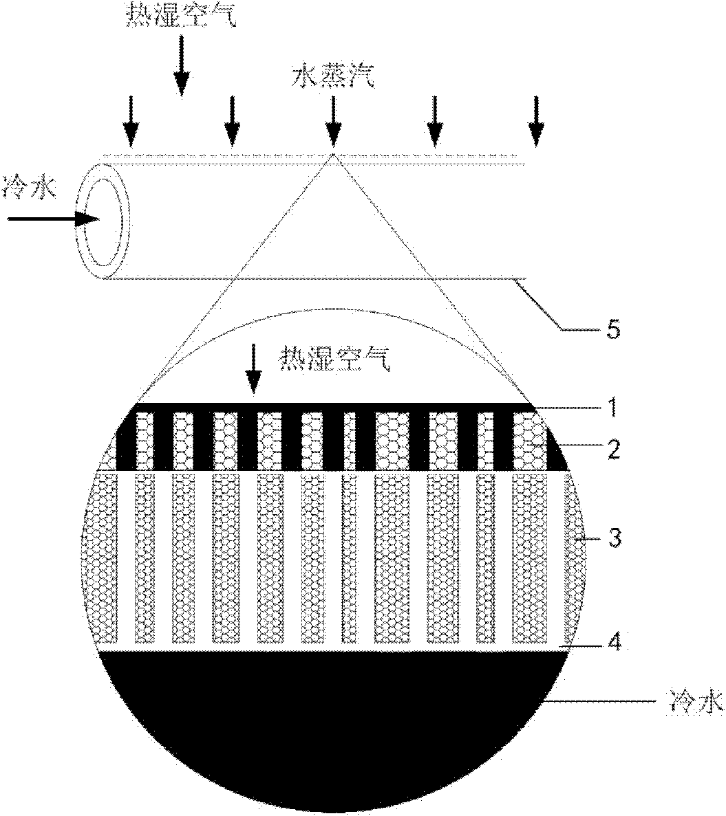
[0014] figure 1 It is a cross-sectional view of a hydrophilic / hydrophobic composite microporous membrane tube 5 according to an embodiment of the present invention. The wall of the hollow membrane tube in the dehumidifier is a hydrophilic / hydrophobic composite microporous membrane structure, and the inner wall of the composite membrane tube is a hydrophobic membrane layer 3, so that the cold water in the tube cannot penetrate to the outside of the tube under normal or low pressure; and The outer wall of the membrane tube is a hydrophilic membrane layer 2, which effectively ensures that the water vapor smoothly enters the micropores in the membrane after condensing on its surface, and the one-way transmission from the outer wall of the membrane tube to the inner wall of the membrane tube.

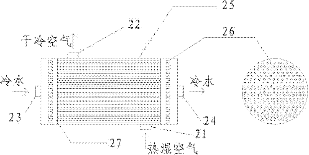
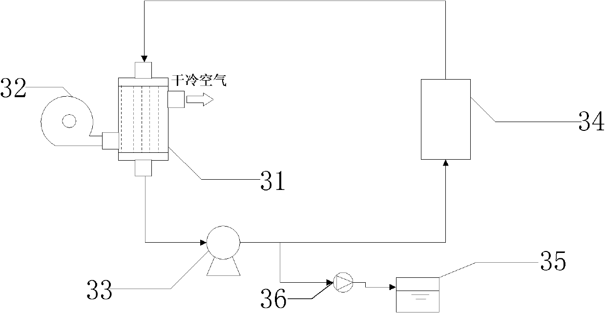
[0015] like figure 2 As ...


PUM


Abstract

The invention provides a novel air cooling and dehumidifying apparatus on basis of hydrophilic / hydrophobic composite microporous membranes. The apparatus is used for controlling temperature and humidity in a spacecraft cabin under microgravity conditions. The apparatus employs a tube-and-shell structure. Low-temperature cold water flows through in numerous membrane tubes; to-be-treated humid air flows through the outsides of the membrane tubes; tube walls of the membrane tubes are hydrophilic-hydrophobic composite, wherein the inner wall of each membrane tube is hydrophobic so as to prevent low-temperature liquid in the tube from penetrating to the outside of the tube at a normal or relatively low pressure; while the outer wall of each membrane tube is hydrophilic, so as to effectively ensure that water vapor cooled on the surface of the outer wall of the membrane tube enters into micropores in the membrane smoothly and condensate water is transmitted unidirectionally from the outer wall of the membrane tube to the inner wall of the membrane tube. With continuous addition of enthalpy of the humid air, the temperature of the low-temperature cold water in the membrane tubes increases; temperature-increased cold water eliminates heat to cosmic space by radiation through a radiation radiator of the spacecraft, so that the temperature is reduced; the water becomes the low-temperature cold water again and can be used circularly by cooling and dehumidification. Water vapor of the humid air enters into cooling water in the tubes after condensation and can be reused.

Description

technical field [0001] The invention proposes a "gas-liquid type" membrane air dehumidification device, which dehumidifies and dehumidifies the hot and humid air in the spacecraft cabin through a hydrophilic / hydrophobic composite microporous membrane, which is "membrane dehumidification and water vapor recovery" under microgravity A new technology that combines two into one. technical background [0002] With the rapid development of the manned spaceflight industry, launching long-term in-orbit spacecraft and space stations and other large spacecraft is a major task that will be completed in the next few years or decades. Among them, how to control the air humidity in these spacecraft cabins reliably, efficiently, energy-saving, and long-term stably, and how to recycle water vapor is one of the key technical problems in the environmental control and life support subsystems of spacecraft and space stations. [0003] The air temperature and humidity control in the spacecraft ...

Claims


Application Information

Patent Timeline
IPC IPC(8): B01D53/26B01D63/00B64G1/46
Inventor 袁卫星刘颖杨波袁修干
Owner BEIHANG UNIV
Learn More