Full hydraulic drive differential horizontal screw centrifuge

A decanter centrifuge, full hydraulic technology, applied in the centrifuge and other directions, can solve the problems of hydraulic oil leakage, small output torque hydraulic joint, large differential speed between the drum and the pusher, etc., and achieve high reliability and extended Long service life, powerful effect

Inactive Publication Date: 2012-12-12
天圣环保工程(成都)有限公司
View PDF6 Cites 9 Cited by
  • Summary
  • Abstract
  • Description
  • Claims
  • Application Information

AI Technical Summary

Problems solved by technology

[0003] One of the purposes of the present invention is to solve the above-mentioned deficiencies, to provide a fully hydraulically driven differential decanter centrifuge, in order to solve the problem of large

Method used


Image

  • Full hydraulic drive differential horizontal screw centrifuge

Examples


Embodiment Construction

[0016] The present invention will be further elaborated below in conjunction with the accompanying drawings.

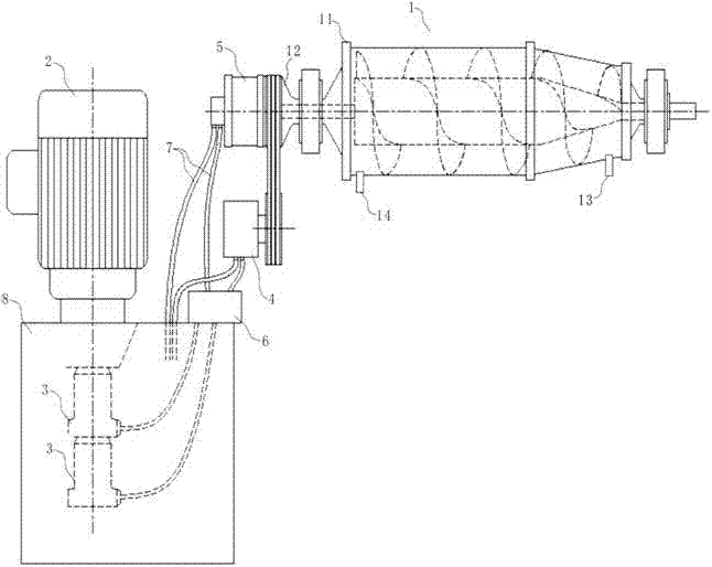
[0017] In the structure of the existing differential decanter centrifuge, the present invention makes further improvements to its driving form. Adjust the rotation differential speed between the drum and the screw pusher to further reduce their differential speed to solve the problem that the material stays in the drum for a short time in the prior art and cause the content of the solid phase material after discharge. The water volume is higher and the wear rate of the auger is accelerated due to the excessive differential speed.

[0018] In view of the above technical problems, figure 1 shows a schematic structural diagram of the present invention, refer to figure 1 As shown, the first embodiment of the present invention is a fully hydraulically driven differential decanter centrifuge, which includes a decanter centrifuge body 1, a drive motor 2 and two hydraulic p...


PUM


Abstract

The invention discloses a full hydraulic drive differential horizontal screw centrifuge, belonging to the horizontal screw centrifuge. The full hydraulic drive differential horizontal screw centrifuge comprises a horizontal screw centrifuge body, a driving motor and at least two hydraulic pumps, wherein the hydraulic pumps are in power connection with the driving motor. The full hydraulic drive differential horizontal screw centrifuge further comprises a hydraulic motor and a hydraulic differential; the hydraulic motor is in power transmission with a rotary drum on the horizontal screw centrifuge body; the hydraulic differential is in power transmission with one end of a screw pusher arranged in the horizontal screw centrifuge body; the hydraulic differential and the hydraulic motor are connected with different hydraulic pumps through circulating pipes; and the circulating pipes are provided with control blocks for controlling the output of the hydraulic oil. The full hydraulic drive differential horizontal screw centrifuge is simple in structure, is superior to the differential horizontal screw centrifuge of the same type in the prior art in the driving form, has high use reliability and wide range of application and is particularly suitable for separating cement, mud and other materials.

Description

technical field [0001] The invention relates to a decanter centrifuge, more specifically, the invention mainly relates to a full hydraulic drive differential decanter centrifuge. Background technique [0002] Decanter centrifuge is a horizontal spiral unloading and continuous operation settling equipment. Its working principle is that the drum and the screw rotate at a high speed in the same direction at a certain differential speed. After entering the drum, under the action of the centrifugal force field, the heavier solid phase is deposited on the drum wall to form a sediment layer. The conveying screw continuously pushes the deposited solid phase to the cone end of the drum, and is discharged out of the machine through the slag discharge port. The lighter liquid phase forms an inner liquid ring, continuously overflows the drum from the overflow port at the large end of the drum, and is discharged out of the machine through the liquid discharge port. At present, decanter...

Claims


Application Information

Patent Timeline
IPC IPC(8): B04B9/06B04B9/10
Inventor 邓亲华邓翔曾建清张波
Owner 天圣环保工程(成都)有限公司
Why Eureka
Try Eureka