
Method and device for monitoring a turbine engine of an aircraft

A turbine engine and aircraft technology, applied in the direction of machines/engines, mechanical equipment, engine components, etc., can solve the problems of low navigation speed, low engine drive, missing, etc., and achieve the effect of life extension

Active Publication Date: 2012-12-12
AIRBUS OPERATIONS (SAS) +1
View PDF5 Cites 4 Cited by
  • Summary
  • Abstract
  • Description
  • Claims
  • Application Information

AI Technical Summary

Problems solved by technology

"windmilling" engine drive (rotation of the engine due to the "windmilling" effect of the air velocity passing through the engine) engine drive is too low or absent if the aircraft is traveling at low speed

Method used


Image

  • Method and device for monitoring a turbine engine of an aircraft
  • Method and device for monitoring a turbine engine of an aircraft
  • Method and device for monitoring a turbine engine of an aircraft

Examples


Embodiment Construction

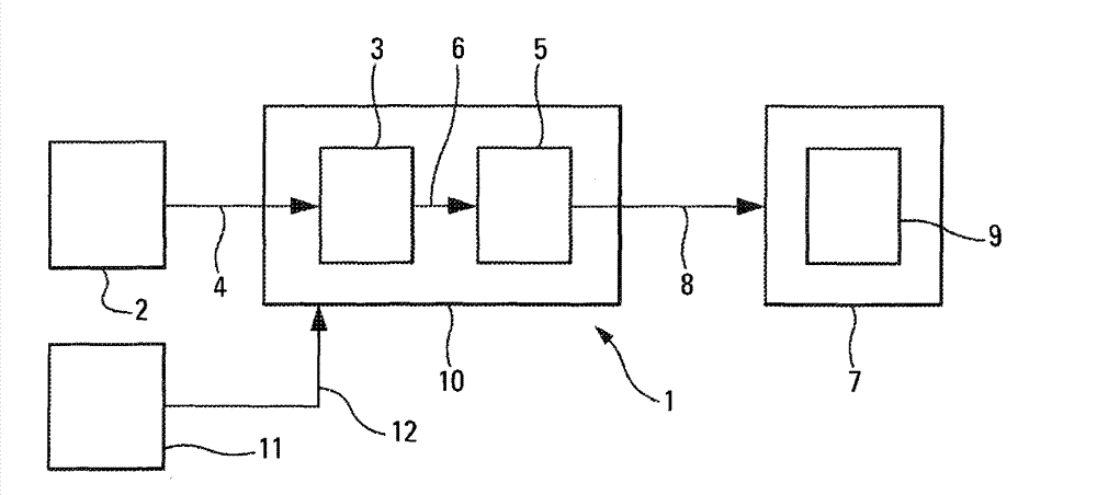
[0048] According to the invention and in figure 1 The function of the device 1 shown schematically in is to assist the crew of an aircraft (not shown), especially a domestic transport aircraft, to monitor at least one turbine engine of the aircraft, such as a turbojet engine or a turboprop engine, which constitutes the propulsion system of the aircraft Part.

[0049] To this end, according to the present invention, the device 1 on board an automatic and aircraft includes:

[0050] -Device 2 for measuring at least current values ​​of parameters related to turbine engines on the aircraft in the usual way, which is detailed below;

[0051] -A device 3, which is connected to the device 2 via a link 4 and is formed to use at least the current value of the above-mentioned measurement to determine a value characterizing the thermomechanical state of the turbine engine;

[0052] -A device 5, which is connected to the device 3 through a link 6, and is formed to combine the value of the thermom...


PUM


Abstract

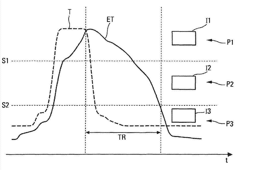
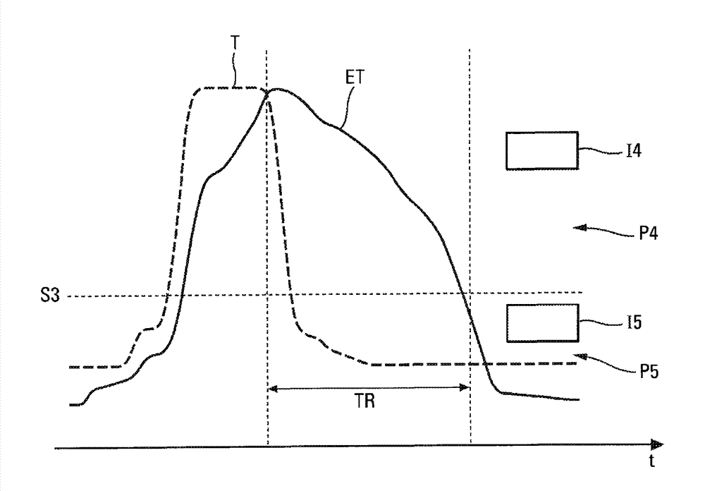
The invention relates to a method and a device for monitoring a turbine engine of an aircraft. The device includes means for determining a value illustrating a thermomechanical state (ET) of the turbine engine, means for comparing this value with at least one threshold (S1, S2) and means for displaying in the cockpit of the aircraft, at least one indication (I1 to I3) related to the operation of the turbine engine, according to this comparison.

Description

Technical field [0001] The invention relates to an auxiliary method and device for monitoring the turbine engine of an aircraft, especially a transport aircraft. [0002] The present invention relates to the detection and processing of differential thermal expansion conditions that can cause rotor lock-up or other mechanical degradation on aircraft turbine engine type engines, as well as to the improvement of the procedures for shutting down and reigniting such turbine engines. Background technique [0003] It is well known that under some operating conditions, due to the differential expansion between the stator and rotor elements, the shutdown of a turbine engine such as a turbojet engine or a turboprop can cause the turbomachinery to lock up. This phenomenon is called "core lock" or "rotor lock". This lockout makes it impossible to restart the engine: during flight, in the case of sudden shutdown but also on the ground, and in the case of early shutdown after landing or for fue...

Claims


Application Information

Patent Timeline
Patent Type & Authority Applications(China)
IPC IPC(8): B64D31/00
CPCF05D2270/303F05B2270/1072Y02T50/671F01D21/003F05D2260/80F05B2260/80F05D2220/323F02C9/00F05B2270/303F02C7/262B64D45/00F05B2220/303F05D2270/092Y02T50/60
Inventor P·热居M·比恩费尔德
Owner AIRBUS OPERATIONS (SAS)
Learn More