Display module and display device

A technology for display modules and display panels, applied in identification devices, frame/frame structures, optics, etc., can solve the problems of wide frame, impact, and inability to press the display panel 900 degrees of liquid crystal display devices, and achieve narrow frame , Improve the effect of the display area

Active Publication Date: 2015-03-11
TCL CHINA STAR OPTOELECTRONICS TECH CO LTD
View PDF5 Cites 0 Cited by
  • Summary
  • Abstract
  • Description
  • Claims
  • Application Information

AI Technical Summary

Problems solved by technology

like figure 2 As shown, since the display panel 900 needs to be pressed by the front frame 100, the front frame 100 needs to be provided with a limiting part 101 to press the display panel 900, and the limiting part 101 needs to face the direction of the display area of ​​the display panel 900 Extend, as shown in the figure, in order to ensure that the front frame 100 can press the display panel 900, the distance that the limiter 101 extends toward the display area of ​​the display panel 900 is h, and the limiter 101 extends toward the display area of ​​the display panel 900 The length h extending in the direction directly affects the design of the narrow frame. If it is shorter, the effect of pressing the display panel 900 cannot be achieved, and if it is longer, the frame of the liquid crystal display device will be wider, which will affect the display range. Therefore, the liquid crystal The structure of the display module needs to be improved urgently

Method used


Image

  • Display module and display device
  • Display module and display device
  • Display module and display device

Examples


Embodiment 1

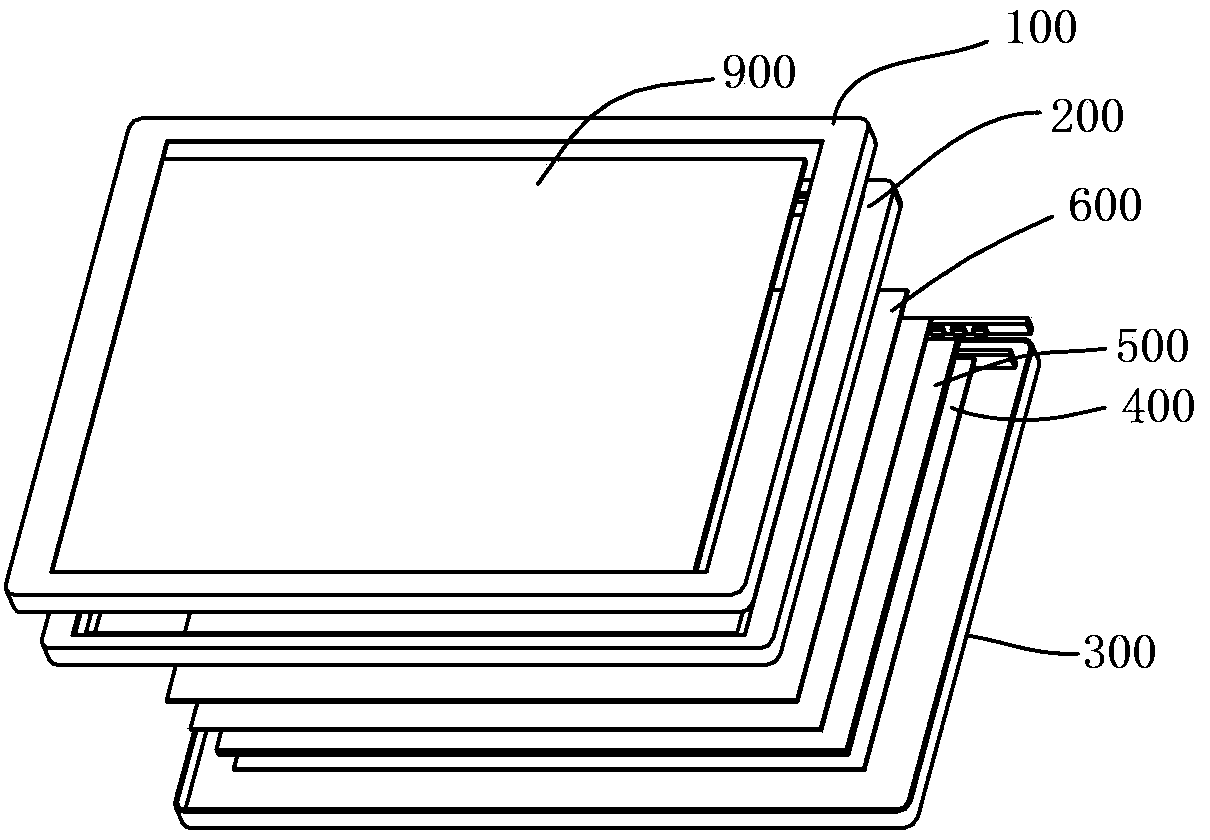
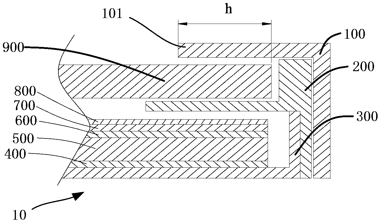
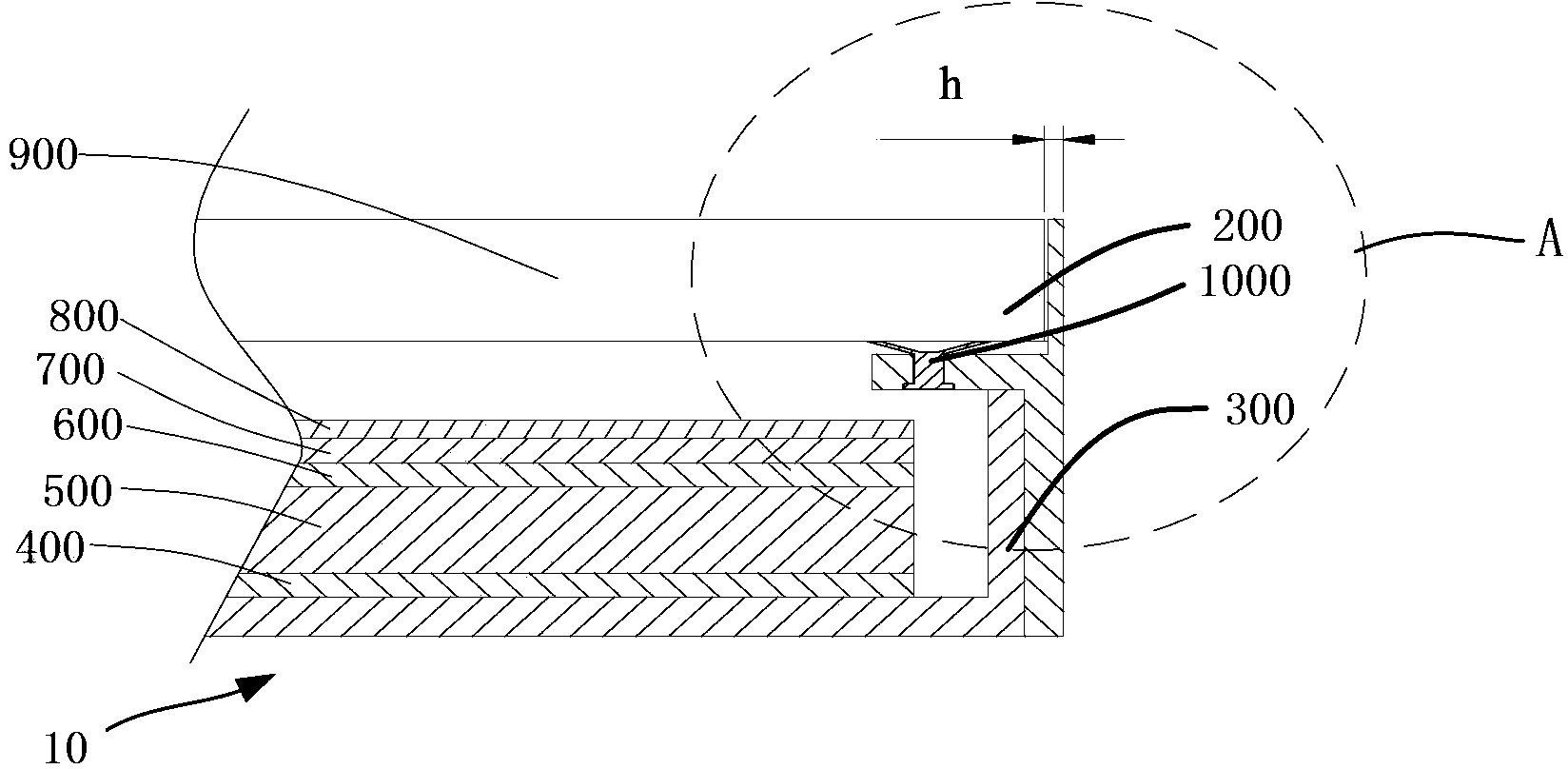
[0027] Such as image 3 Shown is a specific embodiment of the present invention, the liquid crystal display module includes: a backlight module 10 and a display panel 900 disposed on the backlight module 10 . Wherein, the backlight module 10 includes: a backplane 300, a reflection sheet 400 placed in the backplane 300, a light guide plate 500 placed on the reflection sheet 400, a first optical film 600 placed on the light guide plate 500, The second optical film 700 and the third optical film 800 . The backlight module 10 is provided with a frame 200, as shown in the figure, the frame 200 is provided with a bearing part 210 for carrying the display panel 900, and the bearing part 210 is provided with one or more suction cups 1000, the display panel 900 and the light guide plate The opposite rear surface of 500 is sucked by the suction cup 1000 to fix the display panel 900 on the backlight module 10 . When installing the display panel 900, since the lower surface of the displ...

Embodiment 2

[0030] Such as Image 6 and Figure 7 As shown, the difference from the first embodiment is that in this embodiment, the suction cup 1000 is provided with a through hole 1100 for communicating with the atmosphere, and the through hole 1100 is provided with a removable seal 1110 for sealing the through hole 1100 , when the display panel 900 needs to be disassembled, it is only necessary to pull out the sealing member 1110 so that the suction cup 1000 can communicate with the atmosphere, which is convenient and quick.

[0031] Such as Figure 7 As shown, the through hole 1100 and the sealing member 1110 are disposed on the fixing column 1010 , and the structural space of the suction cup 1000 is reasonably utilized.

[0032] Embodiment 1 and Embodiment 2 of the present invention respectively use the display module of the liquid crystal display device to introduce the solution of the present invention. Of course, the solution of the present invention is not limited to the use of...


PUM


Abstract

A display module includes a display panel, and a frame supporting the display panel. The frame is configured with a support structure directly supporting a back surface of the display panel, and the back surface is arranged opposite to a display surface of the display panel. The support structure of the frame is configured with suction cup(s) that holds the back surface of the display panel.

Description

technical field [0001] The present invention relates to the field of flat panel display devices, and more specifically, to a display module and a display device. Background technique [0002] Flat panel displays have become mainstream displays today, including various types such as liquid crystal display devices, plasma display devices, and OLED display devices. The main features of the flat panel display are its thinness and low energy consumption; although the flat panel display is already very thin relative to the CRT display, and has a narrower frame than the CRT display, it still cannot satisfy the consumer's increasing consumer taste. [0003] Taking the liquid crystal display device as an example, the liquid crystal display module is one of the key components of the liquid crystal display device, which is mainly used to provide sufficient brightness, provide uniformly distributed light sources and display images. Such as figure 1 Shown is a liquid crystal display mo...

Claims


Application Information

Patent Timeline
Patent Type & Authority Patents(China)
IPC IPC(8): G02F1/13G09F9/33H05K5/02H05K7/18
CPCG02F2201/46G02F2201/503G02F1/133308G02F1/133603H01L27/32G02F2001/133317G02F1/133317
Inventor 陈仕祥俞刚
Owner TCL CHINA STAR OPTOELECTRONICS TECH CO LTD
Why Eureka
Try Eureka