Broadband circular polarization patch antenna

A patch antenna and circular polarization technology, which is applied to antennas, resonant antennas, antenna grounding devices, etc., can solve problems such as large cross polarization, increase the difficulty of debugging, and affect the application range of antennas, so as to increase the working bandwidth and improve performance. , the effect of reducing the difficulty of debugging

Inactive Publication Date: 2012-12-12
香港城市大学深圳研究院
View PDF4 Cites 27 Cited by
  • Summary
  • Abstract
  • Description
  • Claims
  • Application Information

AI Technical Summary

Benefits of technology

This technology allows for better design by adding extra components on top of existing elements without changing their overall size or requiring more space than necessary. By doing this it makes smaller devices with improved electrical characteristics such as increased signal strength and reduced interference from external sources like radio signals.

Problems solved by technology

This patented technical problem addressed in this patents relates to achieving smaller sizes while maintaining good electrical properties such as wideband operation without compromising their effectiveness due to factors like radiation efficiency caused by circularly oriented linear polarizers.

Method used


Image

  • Broadband circular polarization patch antenna
  • Broadband circular polarization patch antenna
  • Broadband circular polarization patch antenna

Examples


Embodiment Construction

[0029] The present invention will be further described below in conjunction with the accompanying drawings and specific embodiments.
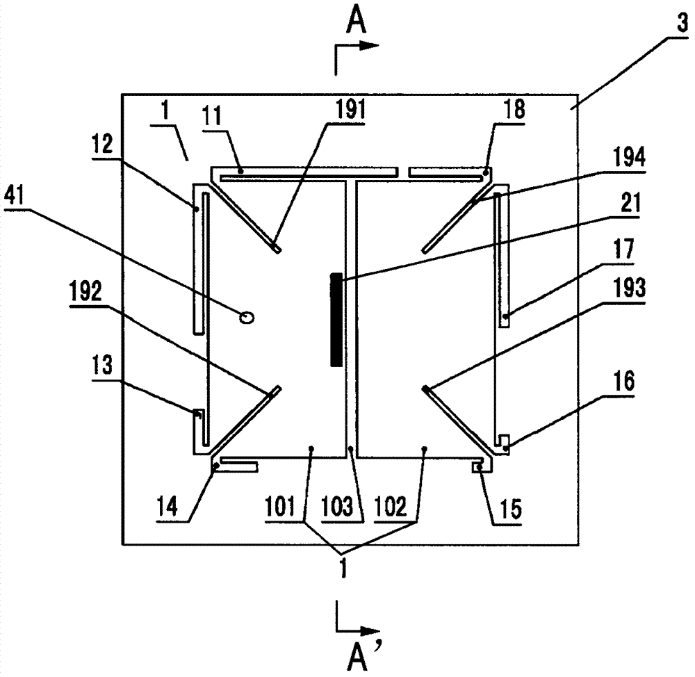
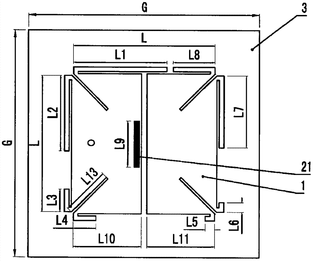
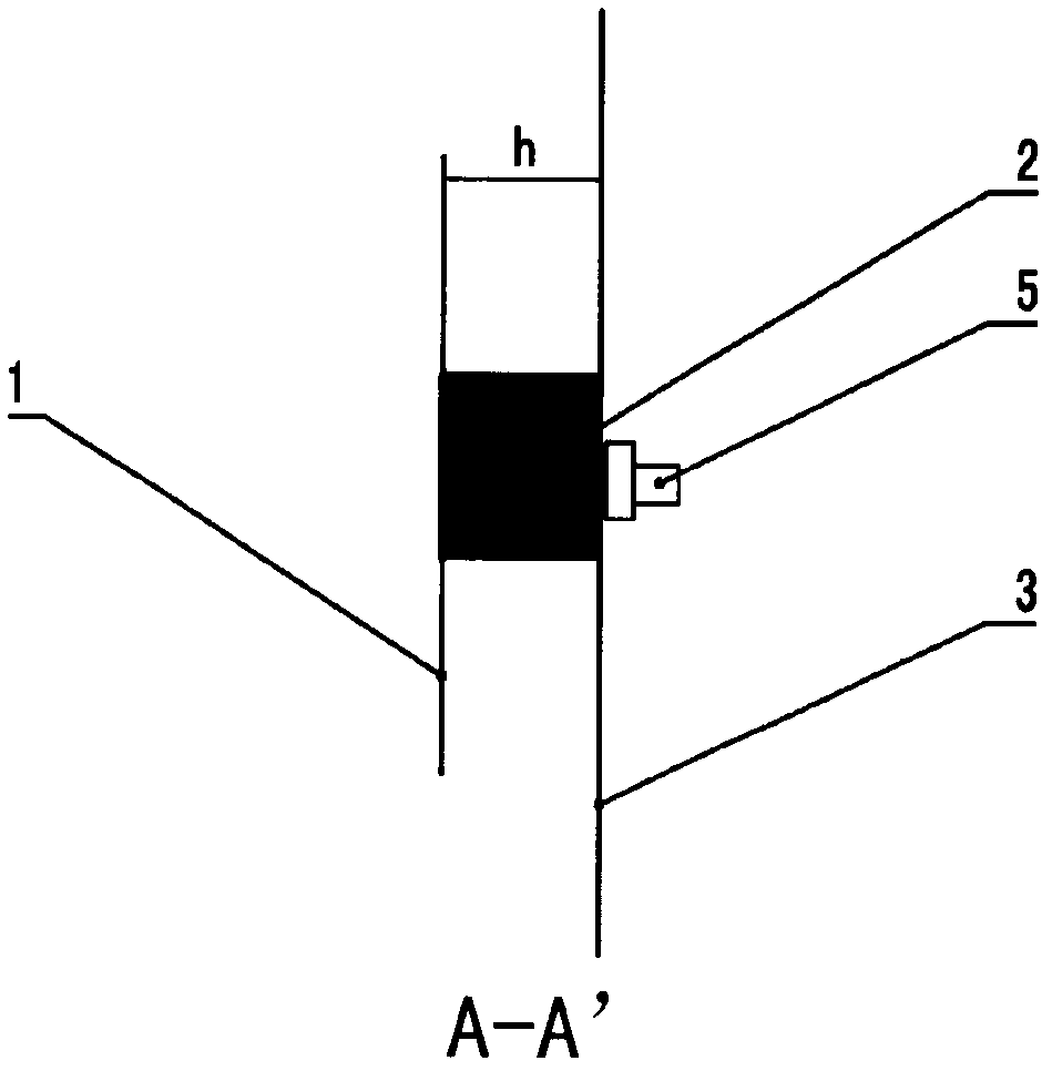
[0030] The design idea of ​​the broadband circularly polarized patch antenna provided by the present invention is: by parasitic a quarter-wavelength patch which is a basic mirror image next to a quarter-wavelength short-circuit ground patch, the whole patch can be excited Two sets of surface currents that are perpendicular to each other, equal in amplitude and approximately 90 degrees out of phase can be produced, so that circularly polarized waves can be excited at two adjacent frequency points, greatly increasing the working bandwidth of the antenna. The broadband circularly polarized patch antenna provided by the present invention can further realize miniaturization, and the miniaturization of the antenna can be realized by covering the above-mentioned antenna patch on a material with a high dielectric constant.

[0031] figure 1 It is a sc...


PUM


Abstract

The invention relates to a broadband circular polarization patch antenna which comprises a metal micro-strip patch (1), a metal grounding plate (3) and a dielectric-slab between the metal micro-strip patch (1) and the metal grounding plate (3). The broadband circular polarization patch antenna is characterized in that the metal micro-strip patch (1) comprises a first metal micro-strip patch (101) and a second micro-strip patch (102) substantially mirrored with the first metal micro-strip patch (101). The first metal micro-strip patch (101) is a quarter-wave grounding short circuit patch with resonant frequency which is f1 and the second metal micro-strip patch (102) is a quarter-wave patch with resonant frequency which is f2, wherein f1 is adjacent to f2 and f1 is smaller than f2. According to the antenna provided by the invention, the working broadband can be enhanced greatly, the performance of the antenna is improved and the debugging difficulty is reduced in practical use.

Description


Claims


Application Information

Patent Timeline
Owner 香港城市大学深圳研究院
Why Eureka
Try Eureka