
Permanent magnet brushless direct current linear motor with structure of rotor screw

A technology of permanent magnet brushless DC and linear motors, applied in the direction of structural connection, electric components, magnetic circuit rotating parts, etc., can solve the problems of poor heat dissipation effect and difficulty in maintaining uniform air gap, and achieve good heat dissipation effect and low voltage The effect of good characteristics and compact structure

Inactive Publication Date: 2012-12-12
HARBIN INST OF TECH
View PDF2 Cites 13 Cited by
  • Summary
  • Abstract
  • Description
  • Claims
  • Application Information

AI Technical Summary

Problems solved by technology

[0003] The purpose of the present invention is to solve the problem that the existing cylindrical linear motor is difficult to maintain uniform air gap, the edge effect caused by the beginning of the magnetic circuit, and the complex device easily leads to poor heat dissipation, and further provides a rotor screw permanent magnet brushless dc linear motor

Method used


Image

  • Permanent magnet brushless direct current linear motor with structure of rotor screw
  • Permanent magnet brushless direct current linear motor with structure of rotor screw
  • Permanent magnet brushless direct current linear motor with structure of rotor screw

Examples


Embodiment Construction

[0012] The present invention will be described in further detail below in conjunction with the accompanying drawings: the present embodiment is implemented on the premise of the technical solution of the present invention, and detailed implementation is provided, but the protection scope of the present invention is not limited to the following embodiments.

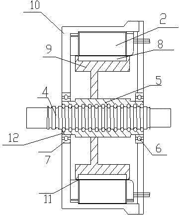
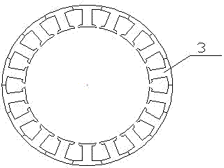
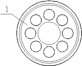
[0013] Such as Figure 1~Figure 5 As shown, a permanent magnet brushless DC linear motor with a rotor screw structure involved in this embodiment includes: a rotor 1 and a stator 2, an air gap 11 is provided between the rotor 1 and the stator 2; the rotor 1 is cylindrical, the rotor 1 is composed of a rotor magnetic steel 8 and a rotor yoke 9, and the rotor magnetic steel 8 is arranged outside the rotor yoke 9; the stator 2 is composed of a stator punch 3 and a casing 10; the present invention also includes A ball screw 4, a screw nut 5, and a support bearing 6. A support bearing 6 is provided between the ball screw 4 and ...


PUM


Abstract

The invention provides a permanent magnet brushless direct current linear motor with a structure of a rotor screw, belonging to the technical field of direct current linear motors. A rotor consists of rotor magnetic steel and a rotor yoke, and the rotor magnetic steel is arranged on the exterior of the rotor yoke; and a stator consists of a stator punching sheet and a main case. The permanent magnet brushless direct current linear motor comprises a ball screw, a screw nut and supporting bearings, wherein a pair of supporting bearings are respectively arranged between the ball screw and the main case, the screw nut is fixed in the rotor yoke, and the ball screw is in threaded connection with the screw nut. The permanent magnet brushless direct current linear motor with the structure of the rotor screw, disclosed by the invention, has the advantages of compact structure, small volume, uniform air gaps and good heat dissipation effect, and quickness, sensitivity and freeness in starting and stopping, and is especially suitable for high-precision linear feed function locations of minitype machine tools or electric tools such as automatic drilling machines, electric screwdrivers and the like.

Description

technical field [0001] The invention relates to a permanent magnet brushless direct-current linear motor with a rotor lead screw structure, belonging to the technical field of linear motors. Background technique [0002] The existing linear motion motor technology needs to use a mechanical device to convert the rotary motion into a linear motion, which causes friction loss in the process, limits the stroke, and limits the development. Although the performance of the world's advanced AC and DC servo systems has been greatly improved, due to the limitation of the traditional mechanical structure feed transmission mode, it is difficult to break through and improve the relevant servo performance indicators. The linear motor direct drive mode cancels all intermediate transmission links between the source power and the worktable components, making the length of the machine tool feed transmission chain zero, so this transmission mode is also called "direct drive" or "zero transmiss...

Claims


Application Information

Patent Timeline
Patent Type & Authority Applications(China)
IPC IPC(8): H02K7/06H02K1/27H02K1/16H02K11/00H02K11/215
Inventor 尚静王剑飞江善林王冰弟
Owner HARBIN INST OF TECH
Learn More