Device for providing a liquid reducing agent

A reducing agent, liquid technology, applied in the direction of exhaust device, noise reduction device, transportation and packaging, etc., to achieve the effect of easy blocking

Active Publication Date: 2012-12-12
EMITEC EMISSIONSTECHNIK
View PDF1 Cites 24 Cited by
  • Summary
  • Abstract
  • Description
  • Claims
  • Application Information

AI Technical Summary

Problems solved by technology

Cleaning the exhaust gas with the aid of the reducing agent introduced constitutes a sign

Method used


Image

  • Device for providing a liquid reducing agent
  • Device for providing a liquid reducing agent
  • Device for providing a liquid reducing agent

Examples


Example Embodiment

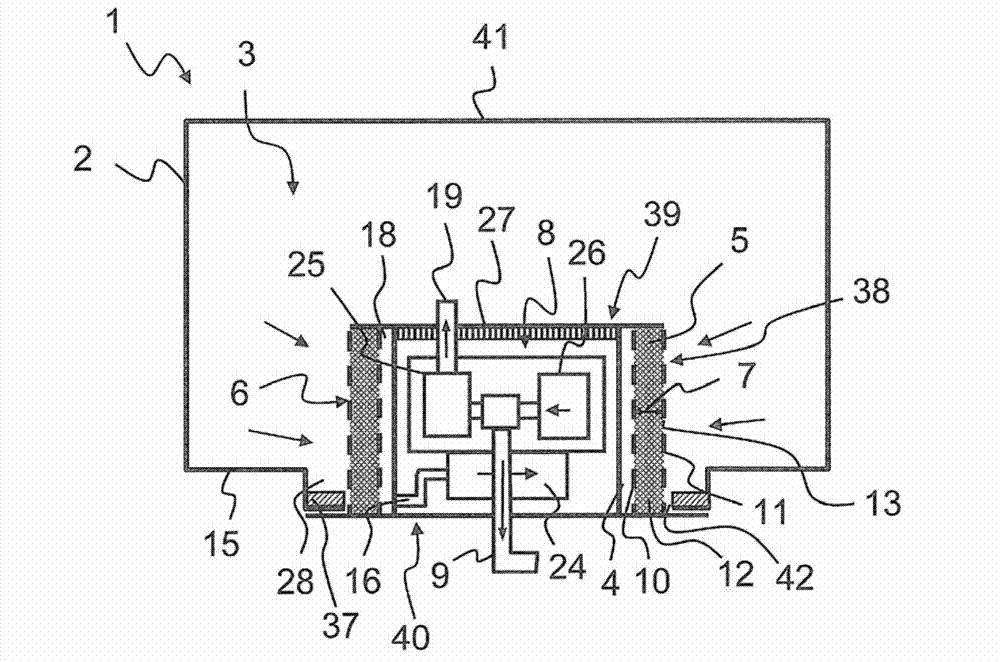
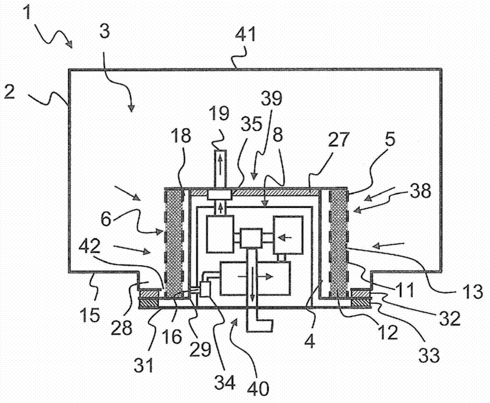
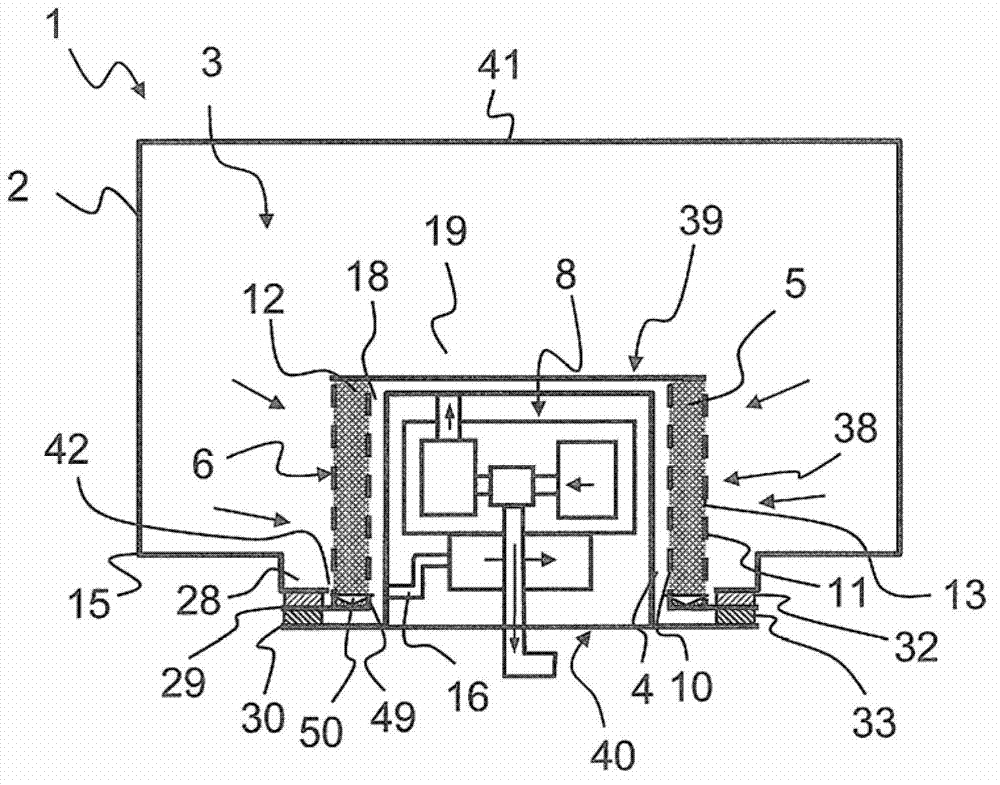
[0057] figure 1 , figure 2 , image 3 , Figure 4 , Figure 5 with Image 6 In other respects, there are parts with the same markings, so here is a general description of these figures. Figure 1 to Figure 4 A vertical sectional view of the device 1 according to the invention is shown in respectively. Figure 5 with Image 6 A horizontal cross-sectional view of the device 1 is shown. The devices 1 each have a storage tank 2 with a storage tank wall 41 which defines the boundary of the internal space 3. On the underside of the storage tank 2, the storage tank wall 41 forms the storage tank bottom 15. There is a storage tank port 42 in the bottom 15 of the storage tank. The container 4 is inserted into the storage tank opening 42, and there is a conveying unit 8 for conveying the reducing agent from the storage tank 2 to the taking place 9 in the container. The taking part 9 is preferably a connector, a pipe or hose can be connected to the connector, and the reducing agent can ...


PUM


Abstract

The invention relates to a device (1) for providing a liquid reducing agent, comprising a tank (2) having an inner chamber (3), and a container (4) arranged at least partially inside said inner chamber (3) of the tank (2). Said container (4) is surrounded on the outside, at least partially by a filter (5) having a filter surface (6) and a filter depth (7), and said container (4) contains a conveyor unit (8) which is configured to extract the reducing agent from the tank (2) through the filter (5) and to guide it to a receiving point (9) for the reducing agent.

Description

technical field [0001] The invention relates to a device for supplying a liquid reducing agent, which has a storage tank for the liquid reducing agent and a device arranged on the storage tank for conveying the liquid reducing agent from the storage tank to a user. Delivery unit for feeding reducing agent to the injector in the exhaust gas treatment system. Background technique [0002] More recently, for cleaning the exhaust gas of (mobile) internal combustion engines, exhaust gas treatment devices have been used more and more, which clean the exhaust gas of the internal combustion engine by means of a reducing agent supplied to the exhaust gas. Mobile internal combustion engines are used, for example, to drive motor vehicles. [0003] For example, selective catalytic reduction methods are known in which the exhaust gas of an internal combustion engine is purified of nitrogen oxides, wherein a medium for reducing nitrogen oxides is supplied to the exhaust gas. Such a medi...

Claims


Application Information

Patent Timeline
IPC IPC(8): F01N3/20
CPCF01N2610/1433F01N3/2066F01N2610/1426Y02T10/24F01N2610/1406F01N2610/1473F01N2610/02Y10T137/794Y02A50/20Y02T10/12F01N3/28F01N3/20
Inventor J·霍格森S·舍佩尔斯
Owner EMITEC EMISSIONSTECHNIK
Why Eureka
Try Eureka