

Transmission method, reception method, transmitter apparatus, and receiver device
A technique of a sending method and a receiving method, applied in the field of sending, receiving, sending device and receiving device, capable of solving problems such as poor performance of waveform distortion compensation, large waveform variation, and wrong estimation results, etc.
- Summary
- Abstract
- Description
- Claims
- Application Information
AI Technical Summary
Problems solved by technology
Method used
Image

Examples
no. 1 approach
[0194] Next, a first embodiment of the present invention will be described.
[0195] A-1. Configuration of the first embodiment
[0196] figure 1 It is a block diagram showing a configuration example of the transceiver according to the first embodiment of the present invention.
[0197] In addition, in the corresponding Figure 28 The same reference numerals are attached to the parts and descriptions are omitted. exist figure 1 Among them, 300 is a semiconductor laser, 301 is a transmitter, 305 is an optical fiber, 306 is a receiver, 309 is a local oscillator laser, 327 is a first inverter, 328 is a second inverter, 329 is a first switch, 330 is the second switch, and 331 is the third switch.
[0198] In the transmitter 301, the first switch 329, the second switch 330, and the third switch 331 are switched in time so that the following signal is input to the second modulator 303 as a Y polarization / I signal: The same signal as the X polarization / I signal of the modulat...
no. 2 approach
[0235] Next, a second embodiment of the present invention will be described.
[0236] B-1. Configuration of the second embodiment
[0237] Figure 8 It is a block diagram showing a configuration example of a transceiver according to the second embodiment of the present invention. In addition, in the corresponding figure 1 The same reference numerals are attached to the parts and descriptions are omitted. exist Figure 8 Among them, 332 is the fourth switch, and 333 is the fifth switch. In that the fourth switch 332 and the fifth switch 333 are provided with an external input terminal for inputting Y polarization / information symbols, it is different from figure 1 The configuration of the transceiver of the first embodiment is shown. Therefore, a baseband signal independent of the X-polarized input signal can be input to the second modulator 303 .
[0238] Regarding information symbols, by performing pseudo-noise (data scrambling) on transmission data in advance, it i...
no. 3 approach
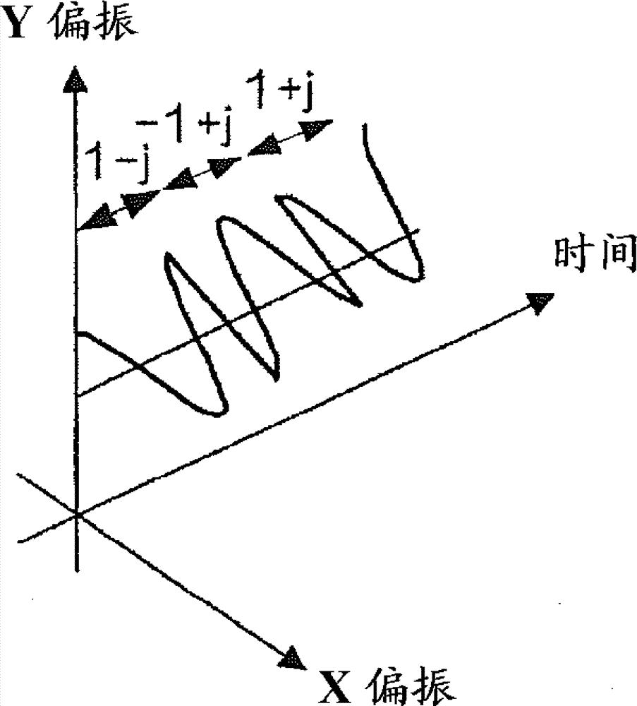
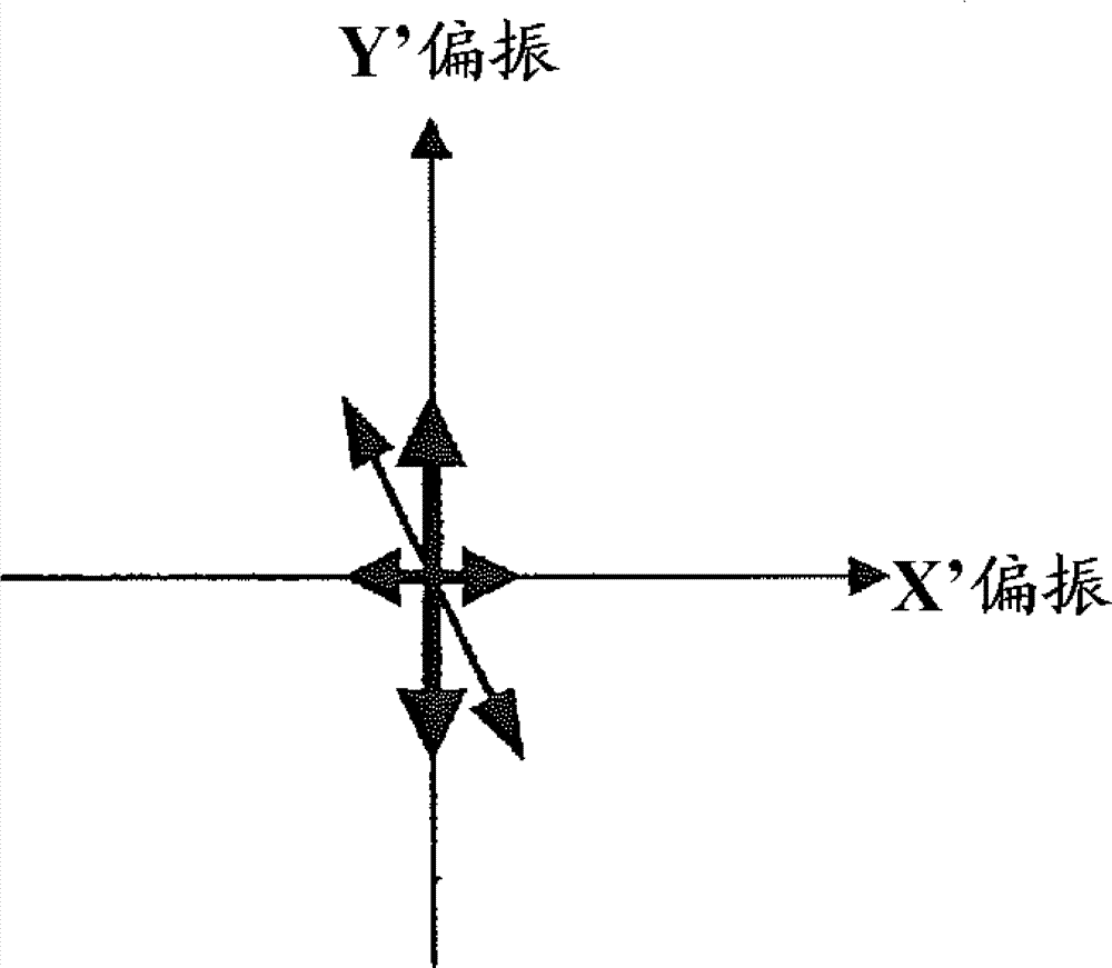
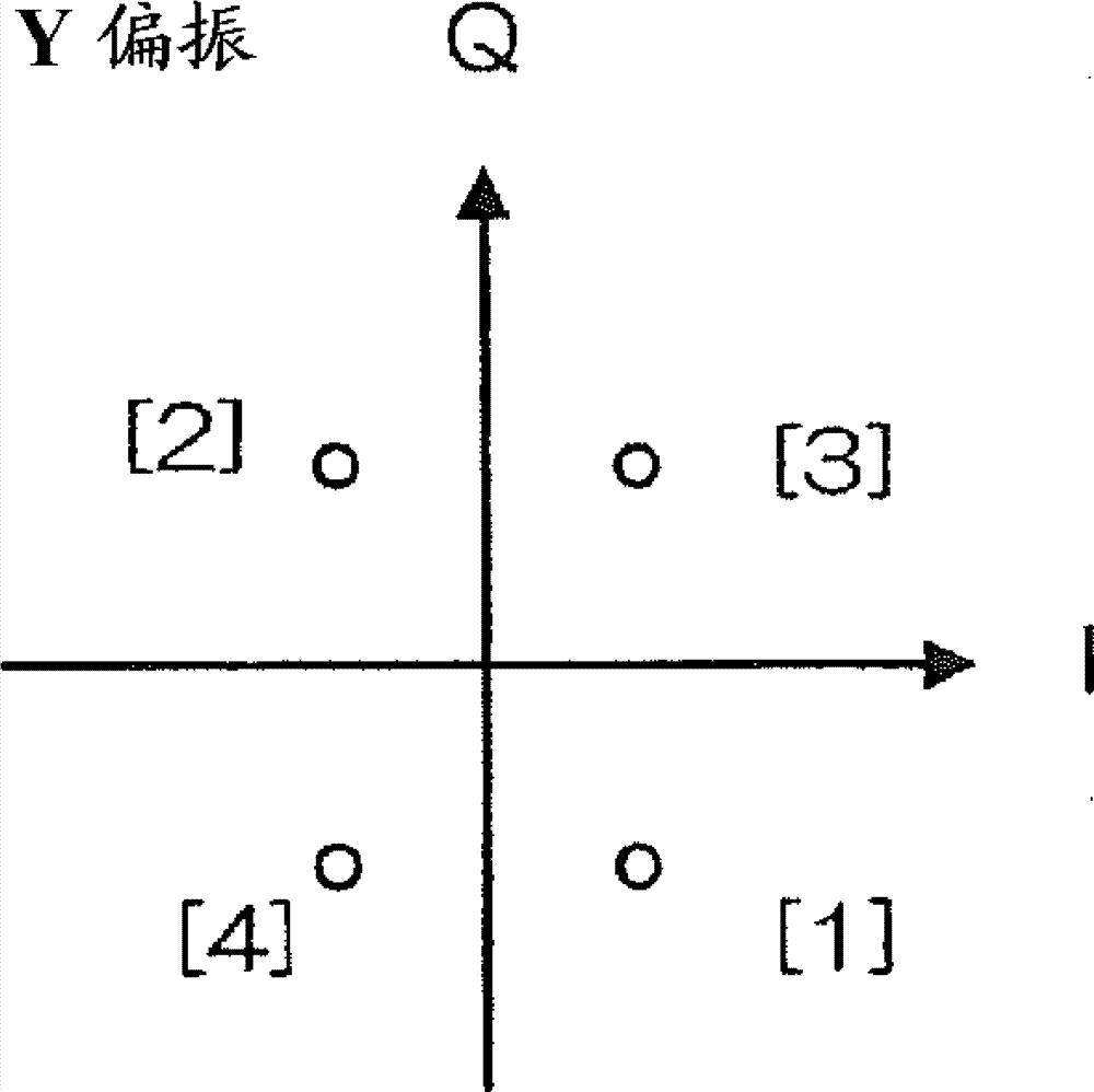
[0267] Figure 12 is a block diagram showing the configuration of the transmitter according to the third embodiment. For each transmission data sequence DS1 ~ DS4, respectively configure insertion circuits 10-1 ~ 10-4 for inserting known signal patterns, and invert a lane of the inserted known signal pattern via digital logic in advance The circuits 11 - 1 , 11 - 2 are inserted to switch ON / OFF of logical inversion at a cycle of sending a known signal pattern. In the case of repeatedly sending the same pattern as a known signal pattern, if the Y-polarized I component and the Y-polarized Q component are as Figure 13 As shown, the logic inversion of converting "1" into "0" and "0" into "1" is repeated, and the on / off is performed every cycle, so that the polarization state can be rotated by 90 degrees every cycle.
[0268]The digital logic inverting circuits 11-1, 11-2 may be inserted in any path. In addition, if ON / OFF of logic inversion is repeated only for the Y-polarized...
PUM
 Abstract
Description
Claims
Application Information