Drive device of electric motor car

A technology for electric motorcycles and driving devices, which is applied to transmission devices, wheel transmission devices, gear transmission devices, etc., can solve problems such as insufficient shift fork fluctuations, poor wheel bearing bearing capacity, and troublesome transmission maintenance, so as to avoid accidental damage. , Small power loss, compact and beautiful appearance

Inactive Publication Date: 2012-12-19
CHONGQING CHENGMOU TECH CO LTD
View PDF7 Cites 5 Cited by
  • Summary
  • Abstract
  • Description
  • Claims
  • Application Information

AI Technical Summary

Problems solved by technology

[0003] The existing rear axle of electric vehicles and motorcycles includes a motor, the input shaft of the motor is provided with a pinion, the pinion is connected with the bull gear through a chain, and the bull gear is connected with the internal rotation body arranged in the rear axle housing, and the internal rotation The body is connected to the half shaft through the half shaft teeth. This structure has the following problems: 1. The chain is easily deformed
However, such a two-speed transmission is not only complex in structure, but also relatively large in size; at the same time, during driving, high and low gears are shifted back and forth, and it is easy to cause off-gear due to improper fluctuation of the shift fork, causing safety hazards for driving.
[0006] And the existing electric motorcycle mainly relies on the rotation of the wheel shaft to drive the wheel hub, so the wheel shaft not only needs to drive the wheel hub to rotate, but also needs to bear the load of the motorcycle, so that the power loss is relatively high, and the load-bearing capacity of the wheel shaft is relatively poor; and the transmission is partially repaired Troublesome, especially the replacement of the motor, it is necessary to dismantle the whole transmission part before repairing or replacing, and because of the trouble of replacing the motor, it is impossible to upgrade the power independently, so as not to meet people's needs

Method used


Image

  • Drive device of electric motor car
  • Drive device of electric motor car
  • Drive device of electric motor car

Examples


Embodiment

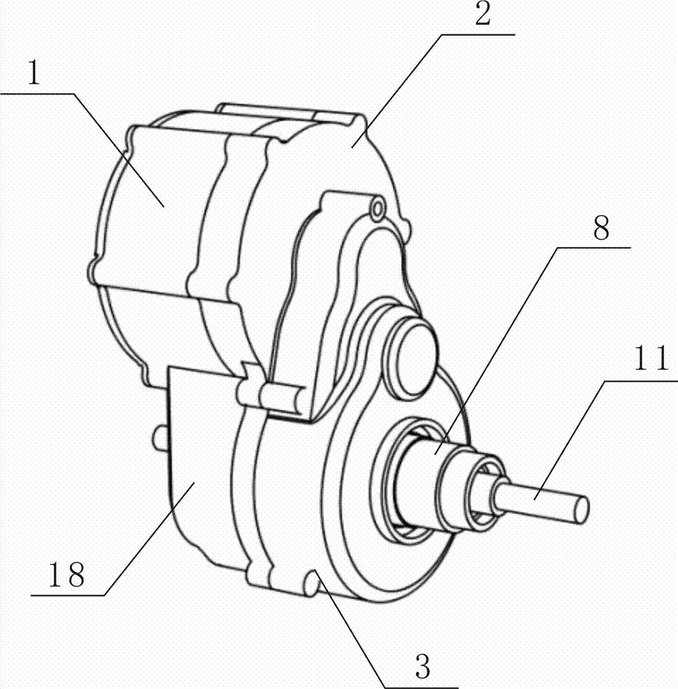
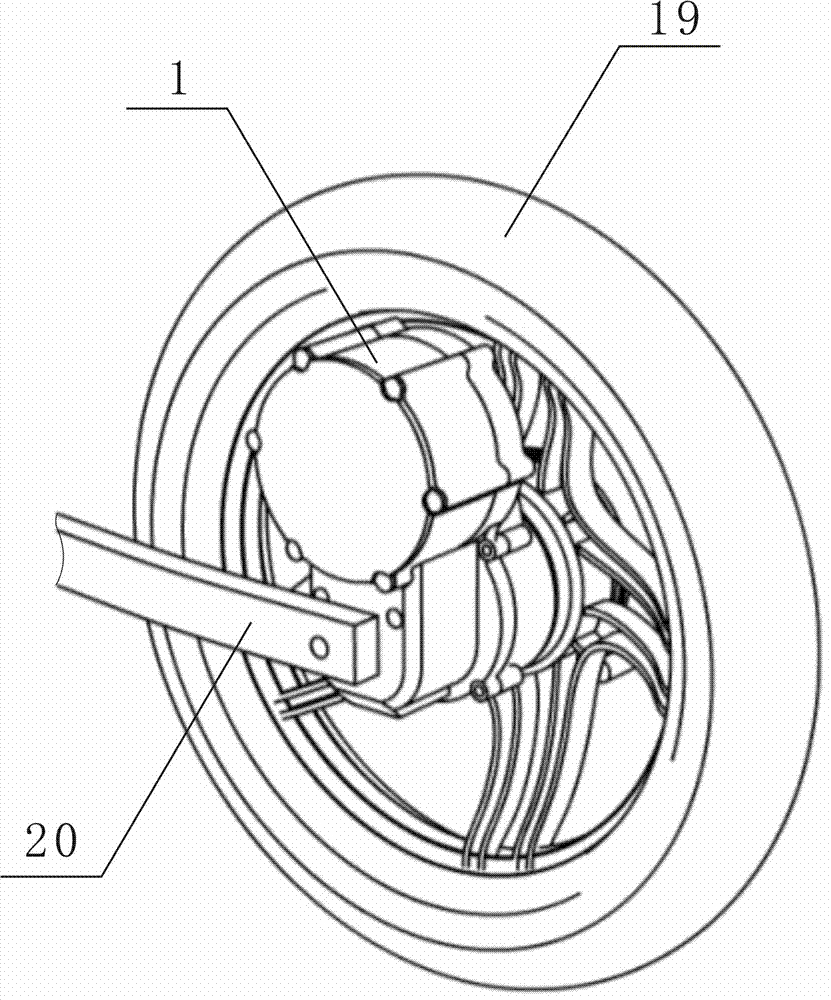
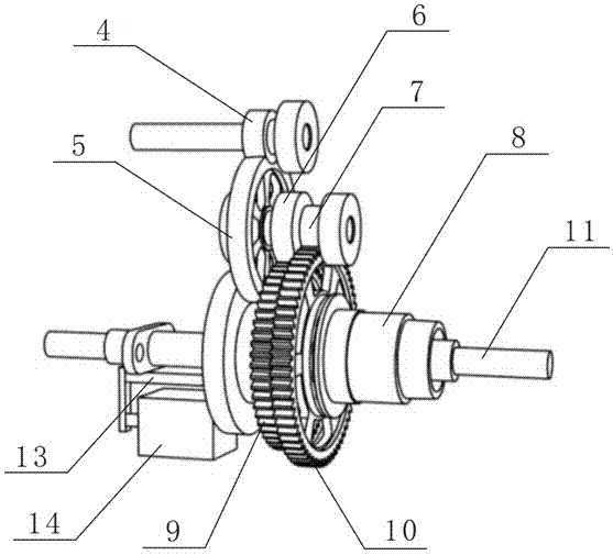
[0034] Example: see Figure 1 to Figure 6 , a driving device for an electric motorcycle, comprising a casing, a motor 1 and a speed change mechanism, the casing includes a vertically arranged mounting plate 2 and a gearbox 3 installed on the lower part of one side of the mounting plate 2, the speed change mechanism is installed In the gearbox 3; the motor 1 is installed on the upper part of the other side of the mounting plate 2 and is detachably connected with the mounting plate 2, and its output shaft passes through the mounting plate 2. During specific production, the mounting plate 2 can be The structure of the upper part is made to be consistent with the end cover of the motor 1, so that when installing the motor 1, the end cover at the output shaft end of the motor 1 can be removed, and the upper part of the mounting plate 2 can be directly used as the end cover of the motor 1, which can be better reduced The volume of the whole driving device is reduced, and it is more ...


PUM


Abstract

The invention discloses a drive device of an electric motor car. The drive device comprises a shell, a motor, a speed change mechanism and a gear-shifting self-holding electromagnet, wherein the speed change mechanism comprises an output shaft sleeve, a high-speed driven gear and a low-speed driven gear are sleeved on the output shaft sleeve, and mutually matched ratchet mechanisms are arranged between the output shaft and the high-speed driven gear and between the output shaft sleeve and the low-speed driven gear. The drive device also comprises a wheel axle, wherein the output shaft sleeve is sleeved on the wheel axle through a bearing, a gear-shifting shaft sleeve capable of moving along the axial direction is sleeved on the wheel axle, the gear-shifting shaft sleeve is matched with the ratchet wheel mechanism by moving the gear shifting shaft sleeve, thus switching between high speed and low speed can be realized. The drive device provided by the invention has the advantages of high gear shifting speed, accuracy and reliability, convenience for maintenance, capability of automatically carrying out power upgrading, low cost, and capability of increasing bearing capacity of the electric motor car.

Description

technical field [0001] The invention relates to an electric motorcycle, in particular to an electric motorcycle driving device. [0002] Background technique [0003] The existing rear axle of electric vehicles and motorcycles includes a motor, the input shaft of the motor is provided with a pinion, the pinion is connected with the bull gear through a chain, and the bull gear is connected with the internal rotation body arranged in the rear axle housing, and the internal rotation The body is connected with the half shaft through the half shaft teeth, and there are the following problems in such a structure: 1. the chain is easily deformed. When the driving time of the electric vehicle is too long, especially when it is loaded with heavy objects, the chain is easily deformed, and the chain may be detached or broken, resulting in the inability of the electric vehicle to drive; 2. Due to the output of the motor The torque is constant, and there is no speed change mechanism in...

Claims


Application Information

Patent Timeline
Patent Type & Authority Applications(China)
IPC IPC(8): B62M11/04F16H3/087
Inventor 李兵彭家洪
Owner CHONGQING CHENGMOU TECH CO LTD
Why Eureka
Try Eureka