
Centring device

A technology of centering device and centering control system, which is applied in the field of centering device for metal strips, can solve the problems of strip edge damage, unreasonable process layout, insignificant deviation correction effect, etc., and achieves a large horizontal horizontal force component. , the correction effect is obvious, the effect of large correction range

Inactive Publication Date: 2012-12-19
上海格林赛高新材料有限公司
View PDF0 Cites 0 Cited by
  • Summary
  • Abstract
  • Description
  • Claims
  • Application Information

AI Technical Summary

Problems solved by technology

[0002] During the process of annealing, pickling and other processes of metal strip, due to the long operation line, only the rectifying devices for retracting and unwinding rings at the machine head and tail cannot meet the normal production, and it is often necessary to install a deviation rectifying device in the middle of the operation line In order to prevent the deviation of the strip, because the strip is thin and has tension, it is not appropriate to use the retaining wheel and the V-shaped wheel to prevent the deviation of the strip, and it is easy to damage the edge of the strip. It is the method of correction roller to carry out intermediate correction, that is, to use the lateral friction force generated by the change of the friction force between the strip and the correction roller to prevent the deviation of the strip and swing The larger the angle and the wider the width of the strip, the greater the lateral friction force will be, and the deviation correction effect will be significant. However, for metal strips with a width of less than 200mm, the deviation correction effect will not be obvious, and the process layout is not reasonable.

Method used


Image

  • Centring device
  • Centring device

Examples


Embodiment 1

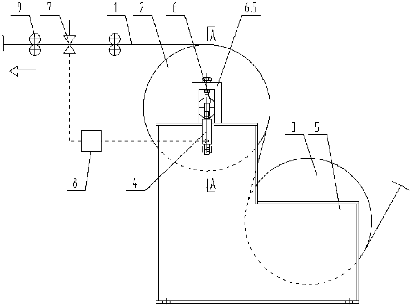
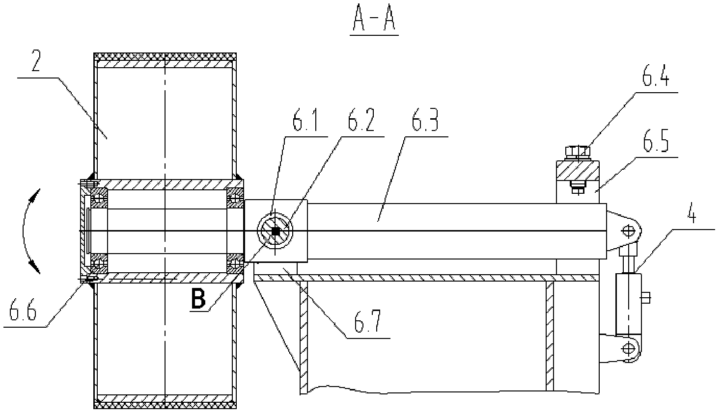
[0016] like Figures 1 to 2 As shown, the device includes a metal strip 1, a correction roller 2, a fixed roller 3, a hydraulic cylinder 4, a machine base 5, a swing shaft device 6, a position sensor 7, a centering control system 8 and a redirecting roller 9. Described swing shaft device 6 is made up of rolling bearing 6.1, fixed shaft 6.2, swing shaft 6.3, adjusting screw 6.4, guide rail device 6.5, rolling bearing 6.6, fixed shaft support 6.7. The deviation-correcting roller 2 and the fixed roller are arranged with upper and lower cantilevers, the deviation-correcting roller 2 is on the top, and the fixed roller 3 is on the bottom. The strip material is wound in an S shape on the deviation-correcting roller and the fixed roller respectively to form a certain package with the roller surface. Angle, the correction roller is installed on the rolling bearing 6.6 of the pendulum shaft 6.3, one end of the pendulum shaft 6.3 cantilevered and can only swing up and down along the ver...


PUM


Abstract

The invention relates to a centring device used in metal strip operation. The centring device comprises a deviation rectifying roller, a fixing roller, a hydraulic cylinder, an engine base, a balance shaft device, a position sensor, a direction changing roller and a centring control system, wherein a strip gets in and out to be wound on the deviation rectifying roller and the fixing roller in an S shape, a certain wrap angle is respectively formed between the strip and the deviation roller and between the strip and the fixing roller, when the strip deflects in operation, the position sensor can send a signal to the centring control system, the centring control system processes and amplifies the signal of the position sensor and instructs the hydraulic cylinder to move up and down, thus the balance shaft swings up and down by taking axis of a fixed shaft as the center along the vertical direction of the axis, the deviation rectifying roller on the balance shaft is driven to swing up and down, and a transverse horizontal component produced between the strip and the deviation rectifying roller is utilized for overcoming deflection of the strip, so as to control the center line of the strip to be close to that of a machine set to the utmost extent. Compared with the prior art, the centring device disclosed by the invention has the characteristics of simple structure, wide deviation rectifying range and fast deviation rectifying speed.

Description

technical field [0001] The invention relates to a centering device for a metal strip, in particular to a centering device for correcting deflection of a metal strip (with a width less than 200 mm) on an operation line. Background technique [0002] During the process of annealing, pickling and other processes of metal strip, due to the long operation line, only the rectifying devices for retracting and unwinding rings at the machine head and tail cannot meet the normal production, and it is often necessary to install a deviation rectifying device in the middle of the operation line In order to prevent the deviation of the strip, because the strip is thin and has tension, it is not appropriate to use the retaining wheel and the V-shaped wheel to prevent the deviation of the strip, and it is easy to damage the edge of the strip. It is the method of correction roller to carry out intermediate correction, that is, to use the lateral friction force generated by the change of the ...

Claims


Application Information

Patent Timeline
Patent Type & Authority Applications(China)
IPC IPC(8): B65H23/038
Inventor 余波杨惟志
Owner 上海格林赛高新材料有限公司
Learn More