Eureka AIR delivers breakthrough ideas for toughest innovation challenges, trusted by R&D personnel around the world.

Coaxial nozzle for laser cladding

A coaxial nozzle and laser cladding technology, which is applied in laser welding equipment, coating, metal material coating process, etc., can solve the problems of damaging the laser emission system, causing danger, and protecting the lens from pollution.

Active Publication Date: 2012-12-19
CHANGZHOU TIANZHENG IND DEV CO LTD
View PDF3 Cites 10 Cited by
  • Summary
  • Abstract
  • Description
  • Claims
  • Application Information

AI Technical Summary

Problems solved by technology

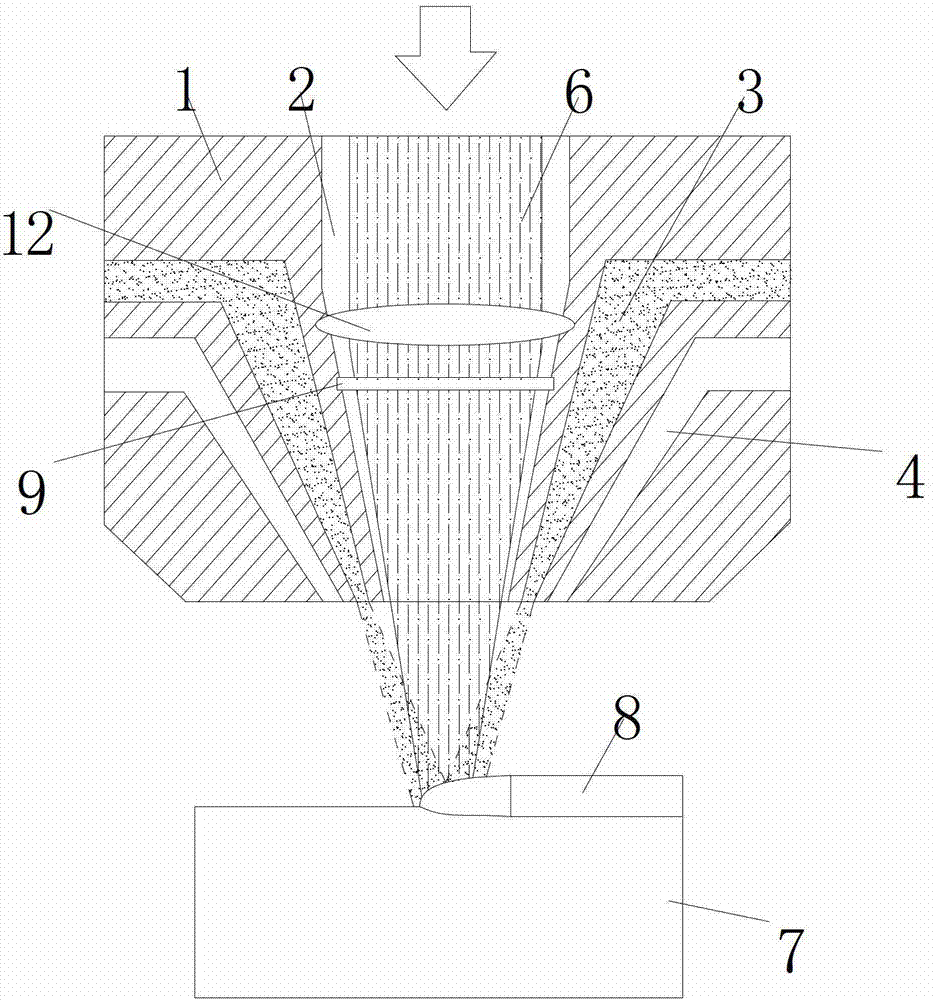
The nozzle is connected under the laser source, and the bottom of the laser source is provided with a protective lens 9 to prevent the powder from entering the laser source. The laser beam 6 enters the nozzle through the laser channel 2 and shoots out. The powder and protective gas flow from the powder channel 3 and the protective gas channel 4 respectively. Since the protective gas channel 4 is set on the periphery of the powder channel 3, when the protective gas is sprayed out, the sprayed powder part will be blown into the laser channel 2, causing danger
When the powder adheres to the protective lens 9, the protective lens 9 is polluted, the light transmission is greatly weakened, and the laser beam 6 cannot pass through the protective lens 9, thereby burning through the protective lens 9
Through the hole where the protective lens is burnt through, the powder may even enter the laser head in reverse and damage the entire laser emitting system

Method used


Image

  • Coaxial nozzle for laser cladding
  • Coaxial nozzle for laser cladding

Examples


Embodiment Construction

[0018] The preferred embodiments of the present invention will be described in detail below in conjunction with the accompanying drawings, so that the advantages and features of the present invention can be more easily understood by those skilled in the art, so as to define the protection scope of the present invention more clearly.

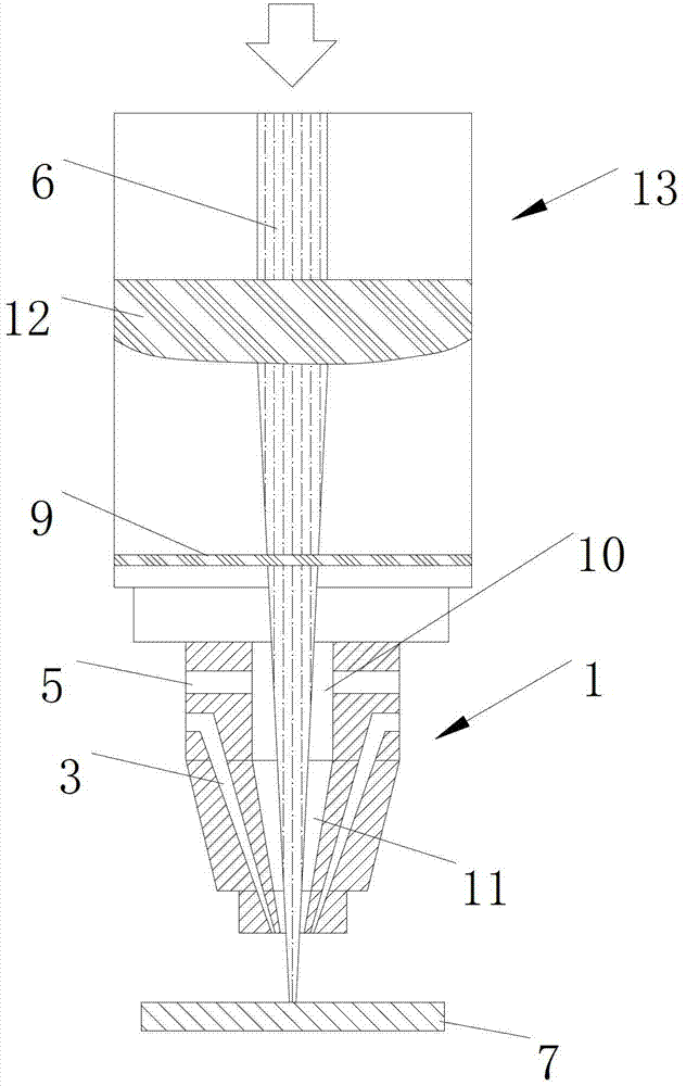
[0019] From attached figure 2 It can be seen from the schematic diagram of the structure that this embodiment provides a coaxial nozzle for laser cladding, which has a central channel that runs through the nozzle 1 up and down in the center of the nozzle 1, and multiple powder channels that are opened around the central channel. 3. The central passage includes the first chamber 10 and the second chamber 11 located below the first chamber 10 and connected to the first chamber 10. The second chamber 11 is funnel-shaped, and the nozzle 1 has an end and a protective gas adding device It is connected with the protective gas inlet 5 whose other en...


PUM


Abstract

The invention discloses a coaxial nozzle for laser cladding, which is provided with a central channel disposed at the center of the nozzle and running through the nozzle from up to down, and a plurality of powder channels disposed at the periphery of the central channel; the central channel comprises a first chamber and a second chamber disposed below the first chamber and communicated with the first chamber; the second chamber is funnel-shaped; a protective gas inlet is disposed on the nozzle, wherein one ee protective gas inlet is connected with a protective gas adding device, and the other end is communicated with the central channel. Laser enters the central channel of the nozzle through a protective lens; high-pressure protective lens enters the central channel through the protective gas inlet, forms flowing wind from up to down in the central channel, is ejected out from the central channel, and mixed with powder ejected from the powder channel to reach a workpiece base material surface to be cladded. With the above technical scheme, the powder is effectively prevented from crushing into the central channel to cause danger, and simultaneously a uniform and symmetric powder flow field is formed.

Description

technical field [0001] The invention relates to a coaxial nozzle for laser cladding, belonging to the field of laser cladding. Background technique [0002] Laser cladding is high-energy laser surface cladding. Its physical process is that under the irradiation of high-energy laser beams, the surface of the substrate is rapidly melted, and the liquid metal forms a small-scale molten pool. In this molten pool, the original metal The material is mixed with the added powder to form a new liquid metal layer. After the laser beam passes through, the temperature of the molten pool decreases, the liquid metal cools rapidly, and a new solid cladding layer is formed on the metal surface. Laser cladding can greatly change the metal properties of this key part, such as hardness, wear resistance, heat resistance, corrosion resistance, etc. [0003] The main powder feeding technology in today's industry in laser cladding applications is side-axis powder spraying. However, since side...

Claims


Application Information

Patent Timeline
Patent Type & Authority Applications(China)
IPC IPC(8): C23C24/10B23K26/14B23K26/34
Inventor 张翀昊柳岸敏黄佳欣黄和芳张祖洪
Owner CHANGZHOU TIANZHENG IND DEV CO LTD
Why Eureka
Eureka Blog
Learn More