Color filter of top luminescent type organic electroluminescent display
A color filter and color technology, applied in the field of pixel arrangement of color filters, can solve problems such as shortening the life of OLED, and achieve the effect of reducing the risk of inaccurate mask alignment
- Summary
- Abstract
- Description
- Claims
- Application Information
AI Technical Summary
Problems solved by technology
Method used
Image
Examples
Embodiment 1
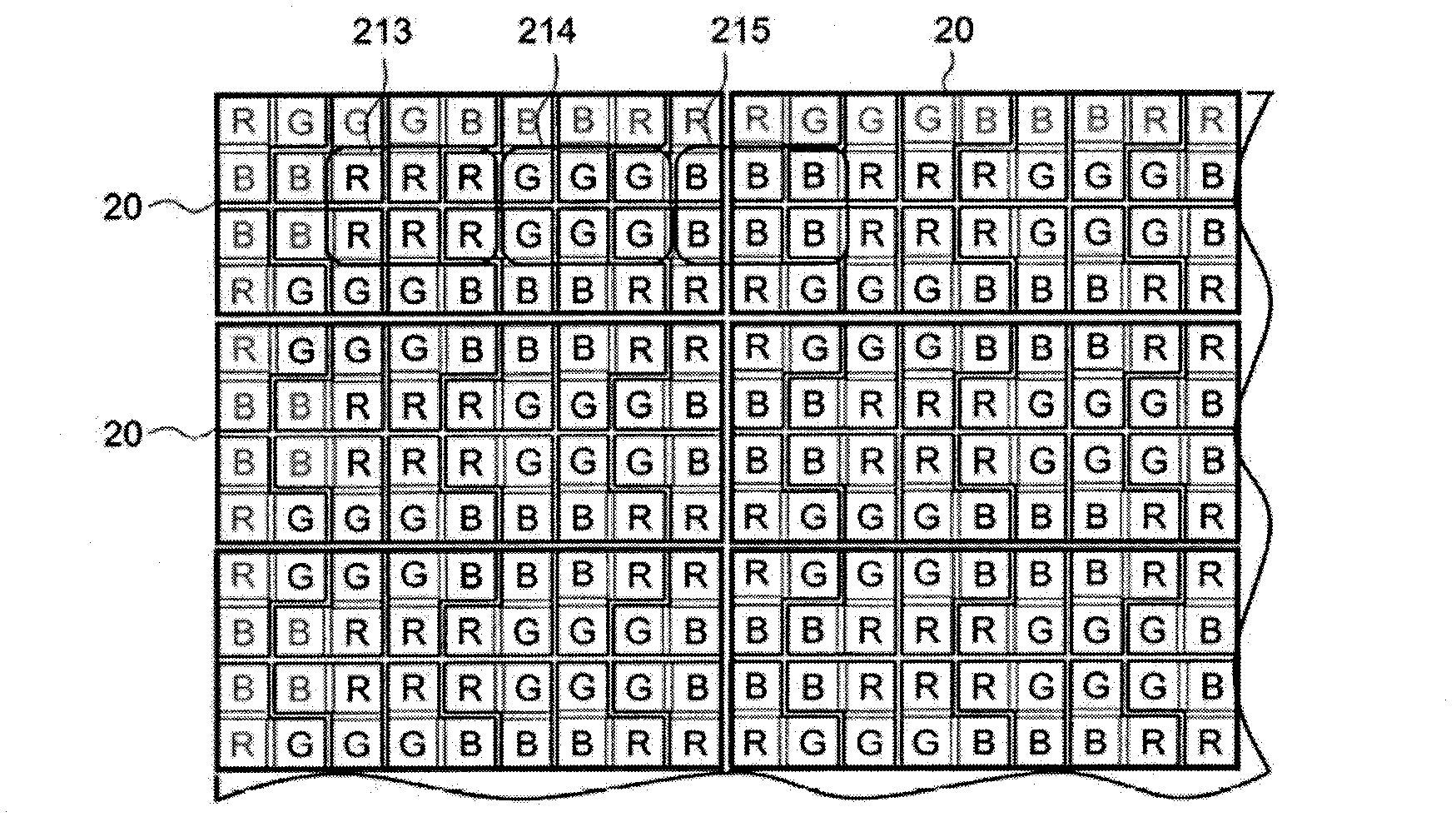
[0038] see Figure 2A and Figure 2B ,in Figure 2A It is a top view of the color filter pixel arrangement of the high-resolution full-color top-emission organic electroluminescence display according to the first embodiment of the present invention; Figure 2B It is a top view of the pixel arrangement of the pixel unit according to the first embodiment of the present invention; Figure 2B The pixel unit 20 shown in is repeated to form Figure 2A The arrangement of color filter pixels is shown.
[0039] See Figure 2B , the pixel unit 20 includes 12 pixels 201, 202, 203, 204, 205, 206, 207, 208, 209, 210, 211, 212 arranged in two rows in a clockwise direction. Each pixel includes a square R sub-pixel, a square G sub-pixel and a square B sub-pixel, and in each pixel, the R sub-pixel, G sub-pixel and B sub-pixel are arranged in an L shape or an inverted L shape. Each pixel in the pixel unit 20 has a different arrangement of sub-pixels. multiple pixels to Figure 2B The show...
Embodiment 2
[0046] Figure 3A It is a top view of the pixel arrangement of the color filter of the high-resolution full-color top-emission organic electroluminescence display according to the second embodiment of the present invention; Figure 3B It is a top view of the pixel arrangement of the pixel unit according to the second embodiment of the present invention; Figure 3B The pixel unit 30 shown in is repeated to form Figure 3A The arrangement of color filter pixels is shown.
[0047] See Figure 3A Figure 3B , the pixel unit 30 includes 8 pixels, namely, 301, 302, 303, 304, 305, 306, 307, 308, which are arranged in two rows in a clockwise direction. Each pixel consists of a square R sub-pixel, a square G sub-pixel and a square B sub-pixel. In each pixel, R sub-pixels, G sub-pixels and B sub-pixels are arranged in an L shape or an inverted L shape. Each pixel in the pixel unit 30 has a different arrangement of sub-pixels, and multiple pixels are Figure 3B The shown "compleme...
Embodiment 3
[0054] Figure 4A It is a top view of the pixel arrangement of the color filter of the high-resolution full-color top-emission organic electroluminescence display according to the third embodiment of the present invention; Figure 4B It is a top view of the pixel arrangement of the pixel unit according to the third embodiment of the present invention; Figure 4B The pixel unit 40 shown in is repeated to form Figure 4A The arrangement of color filter pixels is shown.
[0055] see Figure 4B , the pixel unit 40 includes 8 pixels, namely, 401, 402, 403, 404, 405, 406, 407, 408, which are arranged in two rows in a clockwise direction. Each pixel includes a square sub-pixel R, a square sub-pixel G and a square sub-pixel B, and in each pixel, the R sub-pixel, G sub-pixel and B sub-pixel are arranged in an L shape or an inverted L shape. multiple pixels to Figure 4B The shown "complementary" arrangement, and make the sub-pixels of the same color next to each other, the sub-pix...
PUM
 Abstract
Description
Claims
Application Information
 - R&D
- Intellectual Property
- Life Sciences
- Materials
- Tech Scout
- Unparalleled Data Quality
- Higher Quality Content
- 60% Fewer Hallucinations
Browse by: Latest US Patents, China's latest patents, Technical Efficacy Thesaurus, Application Domain, Technology Topic, Popular Technical Reports.
© 2025 PatSnap. All rights reserved.Legal|Privacy policy|Modern Slavery Act Transparency Statement|Sitemap|About US| Contact US: help@patsnap.com


