Plug wire type connector
A connector and plug-in technology, which is applied in the field of plug-in connectors, can solve the problems of cumbersome and complicated installation and production connections, off-line wires, and short service life, and achieve the goal of simplifying wiring steps, operability, and production Process, efficiency improvement effect
- Summary
- Abstract
- Description
- Claims
- Application Information
AI Technical Summary
Problems solved by technology
Method used
Image

Examples
Embodiment 1
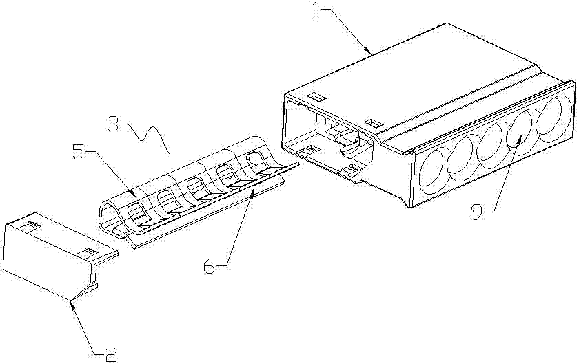
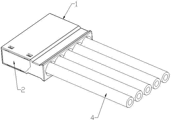
[0051] A plug-in connector described in Embodiment 1 of the present invention, such as figure 1 , figure 2 , image 3 , Figure 4 As shown, it includes a housing 1 and a conductive connecting body 3 placed in the housing. The conductive connecting body is composed of a conductive sheet 6 and an elastic clamping joint assembly 5. The elastic clamping joint assembly is provided with a recessed position, and the conductive sheet is provided with There are protrusions corresponding to the recesses, and the recesses and the protrusions face each other and can cooperate with each other to clamp the wire 4 . The recessed position and the protruding installation position correspond to the front end of the housing. The mutual cooperation of the conductive sheet and the elastic clamping joint assembly can clamp the bare metal end of the wire, and the design of the recessed position and the protrusion can better realize the clamping of the bare metal end of the wire. Of course, the ...
Embodiment 2
[0060] This embodiment 2 is changed on the basis of embodiment 1, specifically: the elastic clamp joint assembly is provided with an opening that can accommodate wires to pass through and fix the corresponding wires so that they do not shift their positions. Resilience clamps the rear end of the connector assembly. The opening is designed so that after the wire is inserted into the connector, one fixed fulcrum of the wire is clamped between the elastic clamp joint assembly and the conductive sheet, and the other fixed fulcrum is formed by the opening. Additionally, if Figure 11 As shown, the shell is divided into upper and lower structures, and the upper and lower structures are both provided with conductive connectors. However, when the connector needs to insert more wires, the use of the upper and lower layer structures can save the use area, which solves the shortcomings of excessive length and excessive use area caused by the horizontal connector.
Embodiment 3
[0062] This embodiment 3 is also changed on the basis of embodiment 1, specifically: as Figure 12 , Figure 13 , Figure 14 , Figure 15 , Figure 16 , Figure 17 , Figure 18 , Figure 19 , Figure 20 , Figure 21 As shown, the elastic clamping joint assembly 5 is provided with a downward-inclining contact, and the conductive sheet 6 is provided with a protrusion corresponding to the downward-inclining contact. The downward-inclining contact and the protrusion face each other and can cooperate with each other to clamp the wire 4. The downward-sloping pressure contact is the end of the top arch of the elastic clamping joint assembly, and the downward-sloping pressure contact is a downward inward slope. The installation position of the downward tilting pressure contact and the protrusion corresponds to the rear end of the housing. The elastic clamping joint assembly is provided with an opening 10 which can accommodate wires to pass through and fix the corresponding wi...
PUM
 Abstract
Description
Claims
Application Information
 - R&D Engineer
- R&D Manager
- IP Professional
- Industry Leading Data Capabilities
- Powerful AI technology
- Patent DNA Extraction
Browse by: Latest US Patents, China's latest patents, Technical Efficacy Thesaurus, Application Domain, Technology Topic.
© 2024 PatSnap. All rights reserved.Legal|Privacy policy|Modern Slavery Act Transparency Statement|Sitemap