Novel three-phase photovoltaic grid-connected inverter system

An inverter, three-phase technology, applied in the field of new three-phase photovoltaic grid-connected inverter system, can solve the problems of low power generation efficiency, low grid-connected voltage, unable to realize grid-connected photovoltaic array, etc. The effect of increasing the voltage on the grid-connected side, improving the utilization rate of light energy and the power generation efficiency of the system

Inactive Publication Date: 2012-12-19
GUANGDONG MINGYANG LONGYUAN POWER ELECTRONICS
View PDF8 Cites 26 Cited by
  • Summary
  • Abstract
  • Description
  • Claims
  • Application Information

AI Technical Summary

Problems solved by technology

[0002] At present, 1MW three-phase photovoltaic power generation system such as image 3 As shown, most of the outputs of two 500kW photovoltaic grid-connected inverters are directly connected in parallel, or as Figure 4 As shown, two 500kW photovoltaic grid-connected inverters are used to realize the parallel connection of two low-voltage windings of a double

Method used


Image

  • Novel three-phase photovoltaic grid-connected inverter system
  • Novel three-phase photovoltaic grid-connected inverter system
  • Novel three-phase photovoltaic grid-connected inverter system

Examples


Example Embodiment

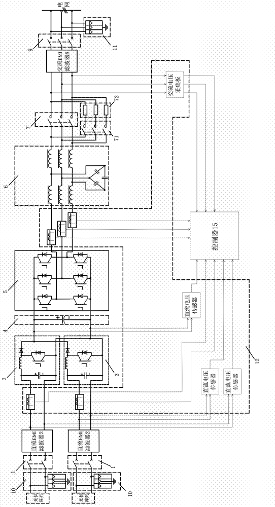
[0028] Example 1, such as figure 1 As shown, there are two photovoltaic arrays, and when the output DC voltage levels are 500V and 700V respectively, each photovoltaic array is boosted by a DC circuit breaker 1, a DC EMI filter 2, and a BOOST boost circuit 3. And the controller 15 perform the maximum power tracking control of the BOOST boost circuit 3, boost the voltage to 960V, and then use the three-phase full-bridge IGBT inverter circuit 5 to perform three-phase inverter and grid-connected power generation, and the grid-connected voltage can be increased Above 620V, through the above structure, two different photovoltaic arrays can be connected to the grid together, which not only expands the maximum power point tracking range, but also improves the DC side voltage and inverter conversion efficiency.

Example Embodiment

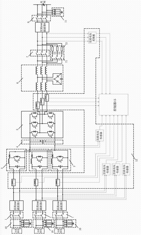
[0029] Example 2, such as figure 2 As shown, there are three photovoltaic arrays, and when the output DC voltage levels are 500V, 700V, 900V, each photovoltaic array is boosted by a DC circuit breaker 1, a DC EMI filter 2, and a BOOST boost circuit 3. The controller 15 performs the maximum power tracking control of the BOOST boost circuit 3, boosts the DC side voltage to 960V, and then performs three-phase inverter grid-connected power generation through the three-phase full-bridge IGBT inverter circuit 5, and The grid voltage can be increased to above 620V. Through the above structure, three different photovoltaic arrays can be connected to the grid together, which not only expands the maximum power point tracking range, but also improves the DC side voltage and inverter conversion efficiency.

[0030] The sine filter 6 described in the above two embodiments uses an LCL sine filter to eliminate harmonics to obtain alternating current with the same frequency as the power grid.

...


PUM


Abstract

The invention discloses a novel three-phase photovoltaic grid-connected inverter system, wherein the system can be combined to grid after outputting the direct current to different photovoltaic arrays to independently boost; the system has good compatibility to the accessed photovoltaic array; the system boosts the corresponding photovoltaic array respectively through the BOOST circuit and tracks and controls the maximum power point of the BOOST circuit through a controller, so that the tracking range of the maximum power point is enlarged, and the direct current side voltage and the inverter conversion efficiency are improved; the system can be combined and connected with different photovoltaic arrays to achieve combination to the grid through single inverter, so the novel three-phase photovoltaic grid-connected inverter system saves cost and improves the voltage of the grid-connected side, and meanwhile, meets different photovoltaic array combination ways and different environmental requirements and improves the light energy utilization rate and the system generating efficiency.

Description

[technical field] [0001] The invention relates to a novel three-phase photovoltaic grid-connected inverter system. [Background technique] [0002] At present, 1MW three-phase photovoltaic power generation system such as image 3 As shown, most of the outputs of two 500kW photovoltaic grid-connected inverters are directly connected in parallel, or as Figure 4 As shown, two 500kW photovoltaic grid-connected inverters are connected in parallel through two low-voltage windings of a double-split step-up box transformer. The grid-connected voltage levels are basically 270V, 300V, and 315V. The voltage is low, and the power generation efficiency of the system is relatively low. The battery module combination of the front stage is required to be unified, and it is impossible to realize the grid connection of multiple photovoltaic arrays with different combination types. In order to meet the grid-connected power generation of different photovoltaic array combinations and improve t...

Claims


Application Information

Patent Timeline
IPC IPC(8): H02M7/5387H02M3/155H02J3/38
CPCY02E10/58Y02E10/563Y02E10/56
Inventor 王建军严长辉于虹陈守信苏潮杨振宇
Owner GUANGDONG MINGYANG LONGYUAN POWER ELECTRONICS
Why Eureka
Try Eureka