Double-switch magnetoresistive motor system based on synchronous drive

A technology of switched reluctance motor and reluctance motor, which is applied in multiple motor speed/torque control, electronic commutator, etc., and can solve problems such as inability to achieve zero error synchronization, increase system cost and volume, and synchronization error

Inactive Publication Date: 2012-12-19
ZHEJIANG UNIV
View PDF2 Cites 12 Cited by
  • Summary
  • Abstract
  • Description
  • Claims
  • Application Information

AI Technical Summary

Problems solved by technology

This system structure cannot achieve zero-error synchronization, because the speed detected by the master motor has a delay in the control time of the slave motor controller, so the traditional two-machine parallel system has a natural synchronization error
At the same time, the traditional two-machine parallel system requires its own power supply and power converter, which greatly increases the cost and failure points of the system
[0006] In the context of wind power or other systems with power generation and mo...

Method used


Image

  • Double-switch magnetoresistive motor system based on synchronous drive
  • Double-switch magnetoresistive motor system based on synchronous drive
  • Double-switch magnetoresistive motor system based on synchronous drive

Examples


Embodiment Construction

[0032] In order to describe the present invention more specifically, the technical solutions and related principles of the present invention will be described in detail below in conjunction with the accompanying drawings and specific embodiments.

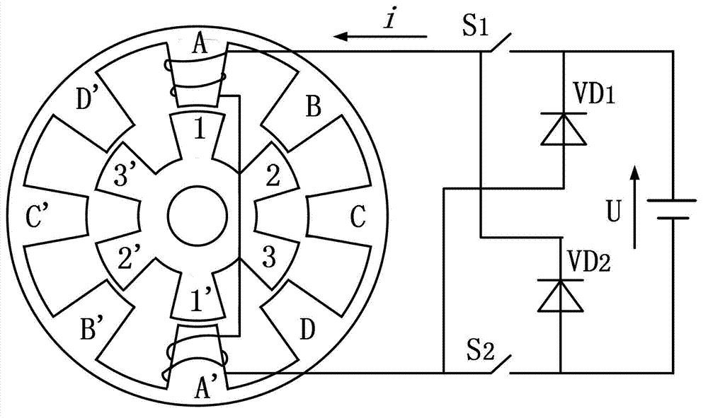
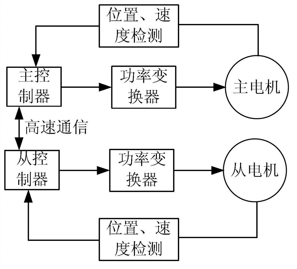
[0033] Such as Figure 4 As shown, a dual switched reluctance motor system based on synchronous drive, including: power converter, battery, position detector, controller, master switched reluctance motor and slave switched reluctance motor, two switched reluctance motors are It is a switched reluctance motor with a three-phase 12 / 8 structure, and the switched reluctance motor with this structure has three stator windings.

[0034] The position detector is used to detect and obtain the position status information of the rotor of the main switched reluctance motor; it is connected to the controller. The shaft of the encoder is connected to the shaft of the main motor. When connecting, align the zero mark of the encoder with the maxim...


PUM


Abstract

The invention discloses a double-switch magnetoresistive motor system based on synchronous drive. The system comprises a power convertor, a direct-current power supply, a position detector, a controller, a main switch magnetoresistive motor and a sub switch magnetoresistive motor, wherein the position detector is used for detecting and acquiring position state information of a rotor of the main switch magnetoresistive motor; the controller is used for constructing and generating a group of driving signals according to the position state information so as to control the power convertor; and the power convertor is used for controlling the connection and the disconnection of each stator winding of the two switch magnetoresistive motors according to the driving signals. The synchronous drive of the two motors can be realized through only one set of power convertor, the main and sub motors synchronously run naturally, and net balance is not caused between the two motors. The power convertor is of the simplest structure, and only one switch tube and only one freewheel diode are required for each phase. When the main motor is in a power generation state and the sub motor is in an electric state, the sub motor can be directly driven without additional intermediate energy decoupling device and power convertor.

Description

technical field [0001] The invention belongs to the technical field of motors, and in particular relates to a synchronously driven double-switch reluctance motor system. Background technique [0002] The motor is a device that converts electrical energy into mechanical energy. According to the different power sources of the motor, it can be divided into DC motors and AC motors. The switched reluctance motor (SRM) is a new type of motor that uses DC power supply. The switched reluctance motor is a double-salient variable reluctance motor. The salient poles of the stator and rotor are laminated by ordinary silicon steel sheets. There is neither winding nor permanent magnet on the rotor, and windings are wound on the salient poles of the stator. SRM can be designed into a variety of structures with different phase numbers, and the number of poles of the stator and rotor has many different combinations. figure 1 A schematic diagram of the four-phase 8 / 6 structure SRM and its po...

Claims


Application Information

Patent Timeline
IPC IPC(8): H02P6/04H02P6/14H02P6/16
Inventor 胡义华邓焰徐惠
Owner ZHEJIANG UNIV
Why Eureka
Try Eureka