
Vacuum clamp for machining thin-plate type part

A technology for parts processing and thin plates, which is applied in the field of vacuum fixtures for thin plate parts processing, can solve problems such as parts deformation and damage, and achieve high processing accuracy

Inactive Publication Date: 2012-12-26
DALIAN VOCATIONAL & TECHN COLLEGE
View PDF10 Cites 26 Cited by
  • Summary
  • Abstract
  • Description
  • Claims
  • Application Information

AI Technical Summary

Problems solved by technology

[0003] The purpose of the present invention is to overcome the above existing problems in the prior art, and to provide a vacuum fixture for processing thin plate parts, so as to solve the problems existing in the processing of thin plate parts, such as easy deformation and damage of parts.

Method used


Image

  • Vacuum clamp for machining thin-plate type part
  • Vacuum clamp for machining thin-plate type part
  • Vacuum clamp for machining thin-plate type part

Examples


Embodiment Construction

[0021] In order to make the purposes, technical solutions and advantages of the embodiments of the present invention clearer, the technical solutions in the embodiments of the present invention will be described clearly and completely below with reference to the accompanying drawings in the embodiments of the present invention:

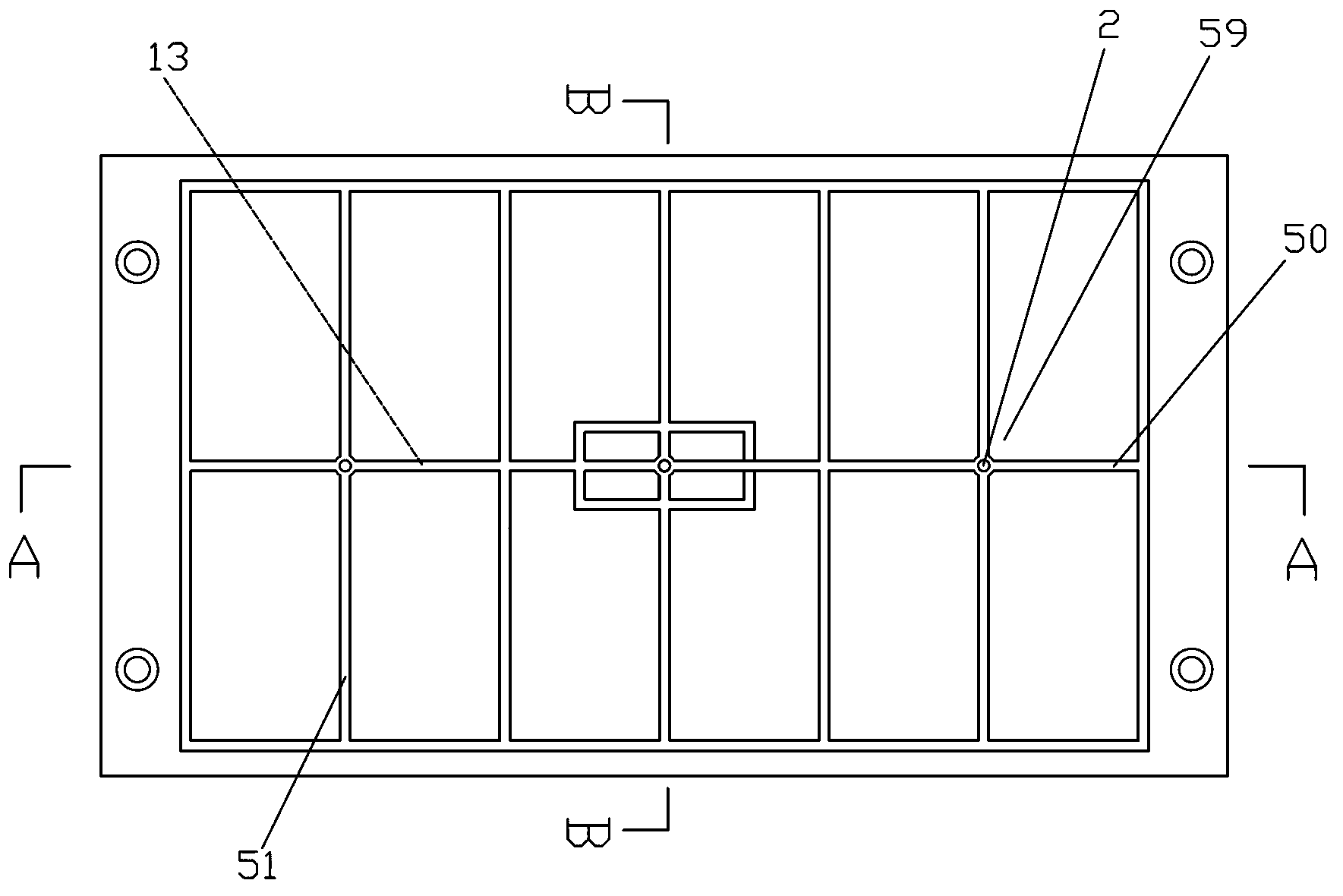
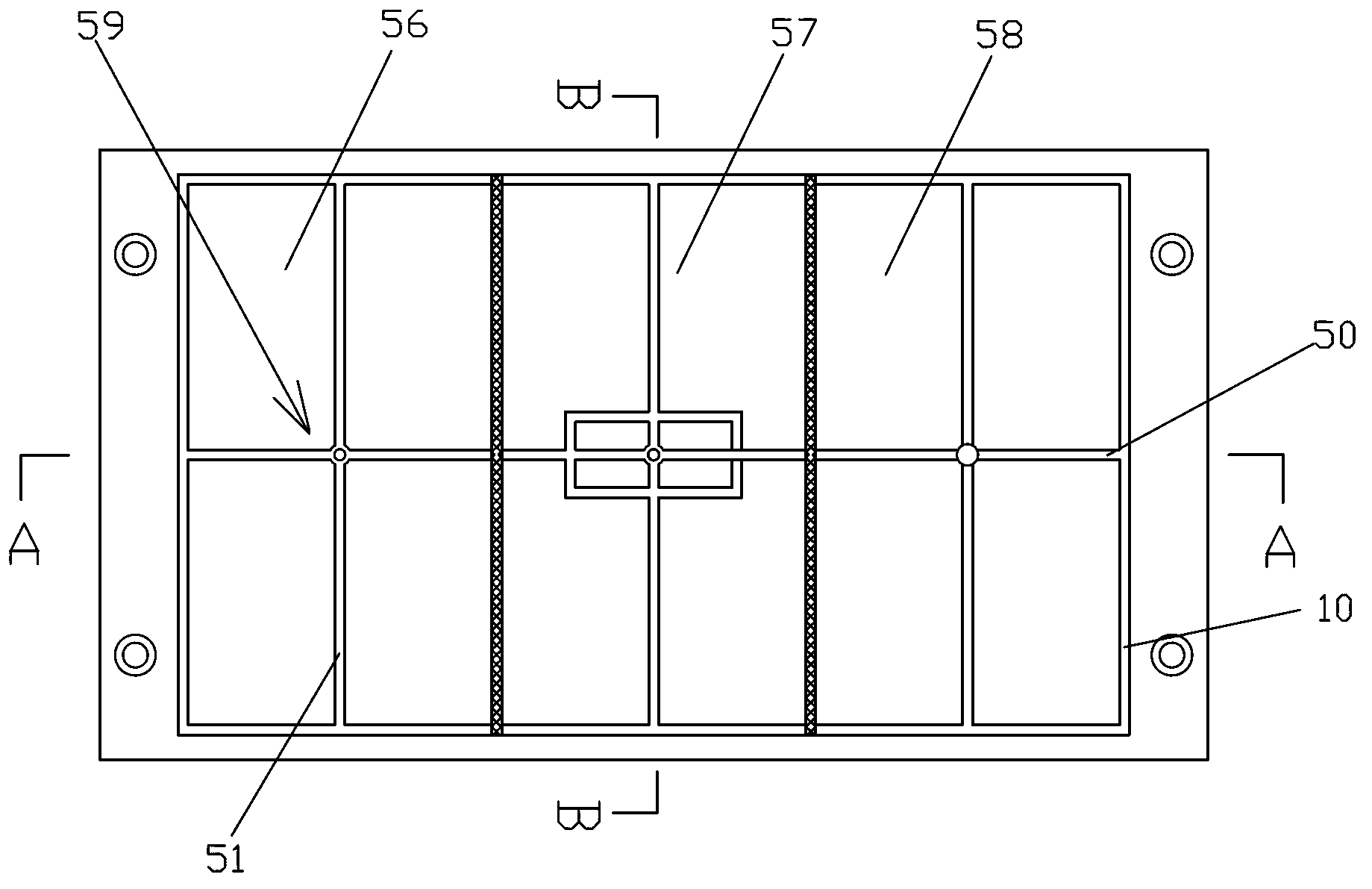
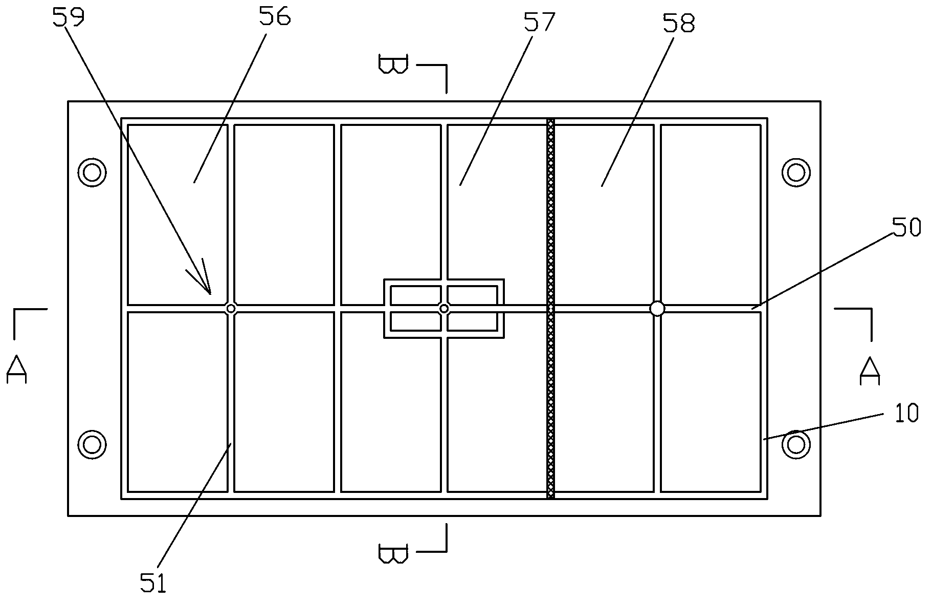
[0022] like figure 1 , figure 2 , image 3 , Figure 4 , Figure 5 , Image 6 and Figure 7 The shown vacuum fixture for thin plate parts processing includes: 1. Bottom plate; 2. Groove control hole; 3. Sealing plug; 4. Sealing strip; 6. Through hole; 7. Sealing cover plate; 8. Bolt 9. Sealing rubber ring; 10. Vacuum adsorption groove; 11. Groove; 12. Annular groove; 13. Groove connected with vacuum adsorption groove, referred to as: connecting groove; 14. Bottom annular groove Slot; 15. Worktable connection hole; 16. Vacuum pump connection hole; 21. Groove control hole I; 22. Groove control hole II; 41. Sealing strip I; 50. Transverse groove; ...


PUM


Abstract

The invention discloses a vacuum clamp for machining a thin-plate type part, comprising a bottom plate provided with a smooth upper surface, wherein the bottom plate is machined with a worktable connecting hole; a vacuum adsorption groove is machined in the bottom plate; the vacuum adsorption groove is an annular groove which is matched with the edge of the bottom plate in shape; a region surrounded by the vacuum adsorption groove is provided with at least one communication groove which is communicated with the vacuum adsorption groove; the vacuum adsorption groove is internally provided with a plurality of groove control holes connected with a vacuum pump; each groove control hole is provided with a sealing plug; and the sealing plugs are detachably connected with the groove control holes. According to the vacuum clamp disclosed by the invention, the principle of the vacuum pump is utilized to adsorb a part to be machined on a vacuum clamp; and when being machined, the part is machined according to the size, so that the higher machining precision is achieved.

Description

technical field [0001] The invention relates to a fixture, in particular to a vacuum fixture for processing thin plate parts used on a numerically controlled milling machine. Background technique [0002] In the existing machining industry, there are many thin plate parts of metal or non-metallic materials. Due to the low rigidity of the parts and the very thin parts required, the use of traditional fixtures for workpieces in the clamping force, cutting force Under the action of factors such as cutting vibration and cutting vibration, the parts are deformed after processing, which cannot meet the processing accuracy; and when the thickness of the plate parts is thin, the existing machine tool fixtures cannot clamp the parts to be processed on the CNC milling machine, and cannot achieve thinner thickness. machining of parts. SUMMARY OF THE INVENTION [0003] The purpose of the present invention is to overcome the above problems in the prior art, and to provide a vacuum fix...

Claims


Application Information

Patent Timeline
IPC IPC(8): B23Q3/08
Inventor 孙德英
Owner DALIAN VOCATIONAL & TECHN COLLEGE
Features
  • Generate Ideas
  • Intellectual Property
  • Life Sciences
  • Materials
  • Tech Scout
  • Unparalleled Data Quality
  • Higher Quality Content
  • 60% Fewer Hallucinations
Learn More