
Stamping forming rod making machine

A rod-making machine and stamping technology, applied in the direction of material forming presses, presses, manufacturing tools, etc., can solve the problems of rapid equipment wear, high temperature of equipment, high energy consumption, etc., to reduce frictional heat and equipment wear Slow, good cooling effect

Active Publication Date: 2016-03-30
山东福航新能源环保股份有限公司
View PDF8 Cites 0 Cited by
  • Summary
  • Abstract
  • Description
  • Claims
  • Application Information

AI Technical Summary

Problems solved by technology

[0002] During the working process of the stamping forming machine, due to the high-speed, high-load movement of the main shaft and the eccentric wheel stamping device, it is prone to high temperature. Using the traditional grease lubrication method, the lubrication effect is poor, the overall equipment is prone to high temperature, and the equipment wears quickly, which cannot meet the use requirements.
At present, energy is in short supply. As a new type of energy, biomass energy has begun to receive great attention. However, how to reduce the volume of this energy, fully burn it, and make it non-polluting. The output of the existing ring die and flat die molding machines is low and the consumption High capacity, unable to meet production requirements

Method used


Image

  • Stamping forming rod making machine
  • Stamping forming rod making machine
  • Stamping forming rod making machine

Examples


Embodiment Construction

[0011] Accompanying drawing is a kind of specific embodiment of the present invention.

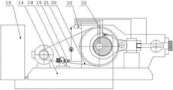
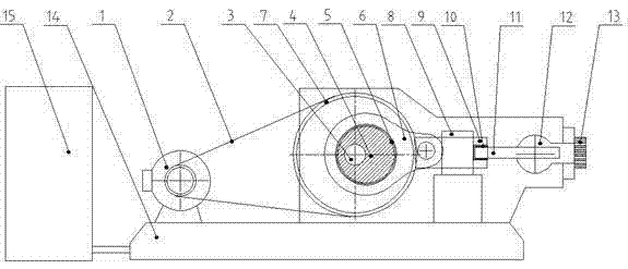
[0012] The stamping type forming rod making machine of the present invention includes a power unit, an extruding device and a forming die 13 installed on the base 14 and connected sequentially, and also includes a lubricating and cooling device, which includes an oil tank 20, an oil pump 19 and a flow rate connected in sequence. Regulating the controller 22, the flow regulating controller is divided into a plurality of branches connected to lubricated and cooled parts, and the lubricated and cooled parts are connected to the oil tank 20 to form a circulating oil circuit.

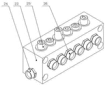
[0013] The lubricating and cooling device also includes an oil pressure sensor 23 located at the lubricated cooling part, and the motor 18 of the oil pump 19 and the oil pressure sensor are respectively connected to the automatic control device 15 . The flow regulating controller 22 is provided with an oil inlet 24 and s...


PUM


Abstract

The invention provides a stamping-type molding stick-making machine comprising a power device, an extruding device and a forming mold, all of which are connected in sequence and arranged on a base; the stamping-type molding stick-making machine further comprises a lubricating and cooling device; the lubricating and cooling device comprises an oil tank, an oil pump and a flow adjusting controller, all of which are connected in sequence; the flow adjusting controller is divided into a plurality of branches connected to lubricated and cooled parts; and the lubricated and cooled parts are connected with the oil tank to form a circulating oil path. The machine has the following beneficial effects that the purpose of multi-oil-path synchronous lubrication can be fulfilled, the friction heat of a moving part can be reduced by oil solution cycling, the lubricating and cooling effects are good, the apparatus is worn slowly, and the problems of high temperature and wearing which frequently occur in the apparatus can be solved well. Meanwhile, the product is small in size, low in energy consumption, high in yield and production efficiency and capable of compacting materials twice, automatically adjusting the feeding amount of the materials, achieving automatic protection function and fulfilling the functions of automatic warning and stopping when in fault.

Description

technical field [0001] The invention belongs to the field of biomass energy processing machinery and relates to a stamping type forming rod making machine. Background technique [0002] During the working process of the stamping forming machine, due to the high-speed, high-load movement of the main shaft and the eccentric wheel stamping device, it is prone to high temperature. Using the traditional grease lubrication method, the lubrication effect is poor, the overall equipment is prone to high temperature, and the equipment wears quickly, which cannot meet the use requirements. . At present, energy is in short supply. As a new type of energy, biomass energy has begun to receive great attention. However, how to reduce the volume of this energy, fully burn it, and make it non-polluting. The output of the existing ring die and flat die molding machines is low and the consumption High performance, unable to meet production requirements. Contents of the invention [0003] In...

Claims


Application Information

Patent Timeline
Patent Type & Authority Patents(China)
IPC IPC(8): B30B11/26B30B15/00B30B15/34B30B15/28
Inventor 王志恒
Owner 山东福航新能源环保股份有限公司
Learn More