Supercharge Your Innovation With Domain-Expert AI Agents!

Biasing circuit and temperature compensation low-frequency amplification circuit for microwave radiometer

A technology of microwave radiometer and bias circuit, which is applied in the field of microwave radiometer, can solve the problems of unable to compensate for the change of the output voltage of the detection diode, unable to compensate for the change of the output voltage of the small signal detection circuit, unfavorable experimental measurement, etc., to solve the problem of temperature noise Interference, low cost, high precision effects

Inactive Publication Date: 2012-12-26
NAT SPACE SCI CENT CAS
View PDF5 Cites 5 Cited by
  • Summary
  • Abstract
  • Description
  • Claims
  • Application Information

AI Technical Summary

Problems solved by technology

Therefore, the measurement results of the microwave radiometer will be greatly changed by the influence of the external temperature, which is not conducive to the experimental measurement.
The reason for this situation is that the output signal of the existing bias circuit is a fixed value or the output terminal of the bias circuit is grounded, which cannot compensate for the change in the output voltage of the detection diode caused by temperature, and cannot compensate for the small The output voltage variation of the signal detection circuit is compensated for

Method used


Image

  • Biasing circuit and temperature compensation low-frequency amplification circuit for microwave radiometer
  • Biasing circuit and temperature compensation low-frequency amplification circuit for microwave radiometer

Examples


Embodiment Construction

[0013] The present invention will be described in detail below in conjunction with specific drawings and embodiments.

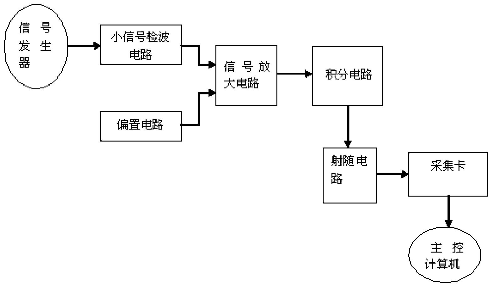
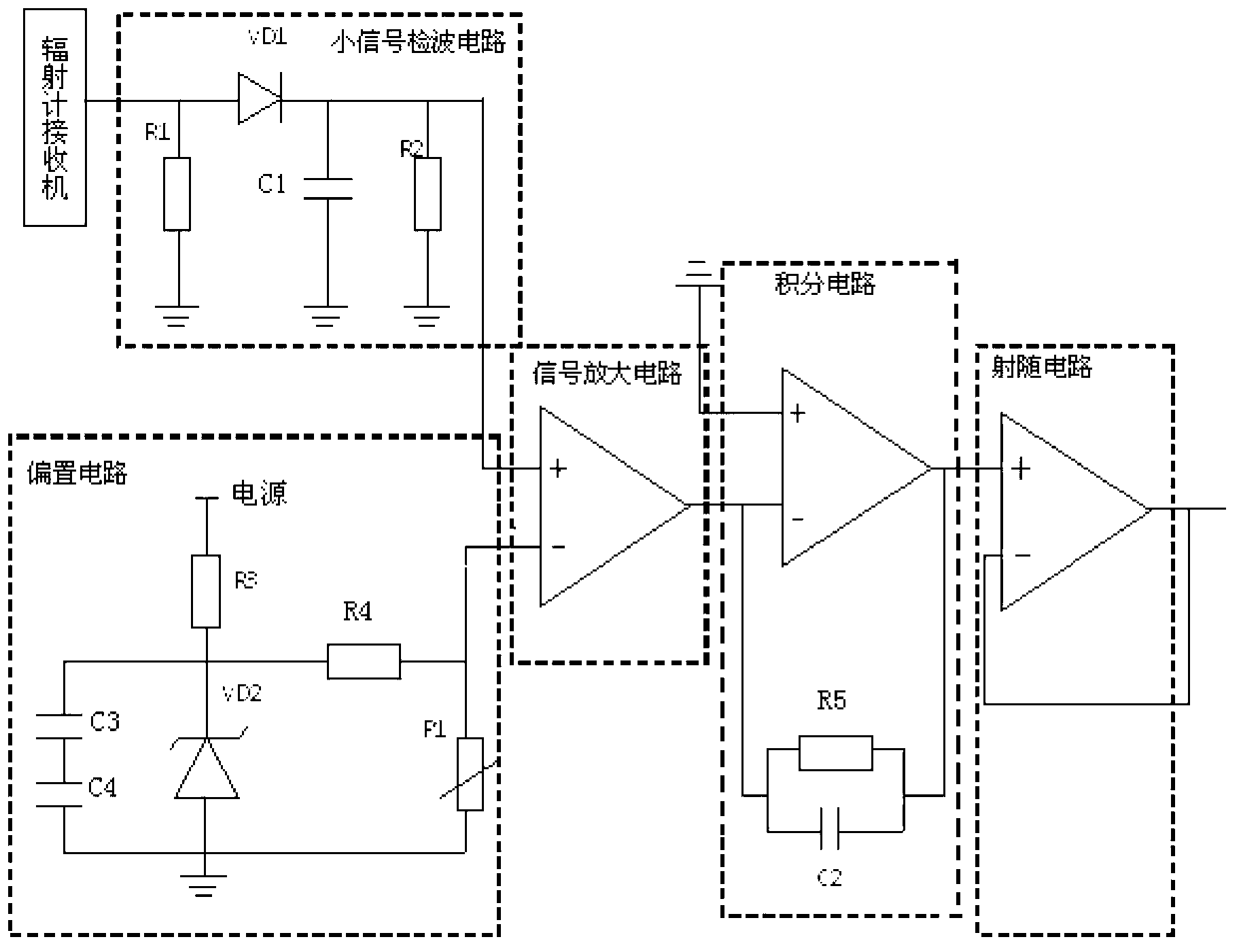
[0014] figure 2 Shown is a schematic circuit diagram of an embodiment of the invention employing a platinum resistor. The temperature-compensated low-frequency amplifier circuit includes a small-signal detection circuit, a bias circuit, a signal amplifier circuit, an integrating circuit, and an emitter-follower circuit (also called a voltage follower).

[0015] The small signal detection circuit includes a detection diode VD1, a resistor R1, a resistor R2 and a capacitor C1, wherein the anode of the detection diode VD1 is respectively connected to the output terminal of the radiometer receiver and the resistor R1, and the other end of the resistor R1 is grounded, and the resistor R1 is the detection diode VD1 provides the turn-on voltage; the cathode of the detection diode VD1 is respectively connected to the capacitor C1, the resistor R2 and an input termi...


PUM


Abstract

The invention relates to a biasing circuit for a microwave radiometer and a temperature compensation low-frequency amplification circuit comprising the biasing circuit. According to the biasing circuit, one end of a resistor R3 is connected with a power supply, the other end of the resistor R3 is connected with a negative electrode of a voltage stabilization diode VD2; a positive electrode of the voltage stabilization diode VD2 is grounded; the power supply, the resistor R3 and the voltage stabilization diode VD2 form a current loop; a capacitor C3 and a capacitor C4 are connected in series to form a series circuit; the series circuit is connected in parallel with two ends of the voltage stabilization diode VD2; one end of a resistor R4 is connected with the negative electrode of the voltage stabilization diode VD2, and the other end of the resistor R4 is connected with a thermistor; the other end of the thermistor is grounded; the resistor R4 and the thermistor form a series circuit; and the series circuit is connected in parallel with two ends of the voltage stabilization diode VD2. The biasing circuit can compensate output voltage change caused by temperature change of a low-signal detection circuit, has a good temperature control effect and reduces influence of outside temperature on the amplification circuit.

Description

technical field [0001] The invention relates to a microwave radiometer, in particular to a bias circuit and a temperature-compensated low-frequency amplifier circuit for the microwave radiometer. Background technique [0002] The microwave radiometer is a passive ground-based passive microwave remote sensing device. A microwave radiometer generally includes four basic components, namely: optical system, detector, amplifier, recording and display device, reference radiation source and modulator. After the radiometer system is integrated, when it is used for open-air measurement, the change of temperature will cause the change of the parameters of the detection diode in the small signal detection circuit of the amplifier, especially the voltage drop at both ends of the detection diode will change with the temperature, making the work of the detection diode Point (that is, Q point) changes, which in turn affects the output voltage of the small signal detection circuit to chang...

Claims


Application Information

Patent Timeline
IPC IPC(8): G01J5/52H03F1/30
Inventor 张江漫张升伟王新彪何杰颖张瑜
Owner NAT SPACE SCI CENT CAS
Features
  • R&D
  • Intellectual Property
  • Life Sciences
  • Materials
  • Tech Scout
  • Unparalleled Data Quality
  • Higher Quality Content
  • 60% Fewer Hallucinations
Learn More