Pendulum bob-type impact response spectrum testing bed

An impact response spectrum and test bench technology, which is applied in the field of pendulum impact response spectrum test benches, can solve the problems of uneven lifting of the pendulum, large interference of the test piece, slow lifting speed of the pendulum, etc., and achieves high waveform repetition consistency. , Improve the test efficiency and improve the effect of waveform quality

Active Publication Date: 2012-12-26
BEIJING AREOSTANARD NEW TECH +2
View PDF11 Cites 14 Cited by
  • Summary
  • Abstract
  • Description
  • Claims
  • Application Information

AI Technical Summary

Problems solved by technology

However, there are many problems in this principle: (1) The lifting speed of the pendulum is slow, and one test needs to lift the electromagnetic or pneumatic pawl twice
(2) When the speed of the pendulum is high, after the first collision, the rebounding pendulum will hit the test table in reverse motion again to form a secondary collision, which may cause overtesting of the test piece.
(3) No table reset device, poor waveform consistency
Jag-type electromagnetic clutch cannot prevent secondary impact, and the magnetic flux leakage is very large, which greatly interferes with the test piece; in the case of power failure, the clutch fails, the pendulum falls, and the reliability is low
With hydraulic motor and disc brake, the lifting of the pendulum is not stable, and the height of the pendulum cannot be modified after the lifting is completed, and the hydraulic oil source is increased, resulting in high power consumption, loud noise, and difficult maintenance

Method used


Image

  • Pendulum bob-type impact response spectrum testing bed
  • Pendulum bob-type impact response spectrum testing bed

Examples


Embodiment Construction

[0024] The present invention will be described in further detail below in conjunction with the accompanying drawings and embodiments.

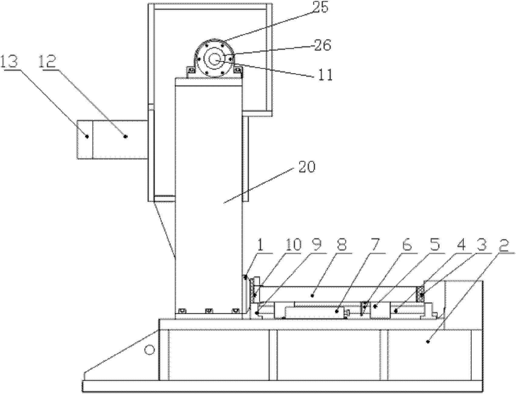
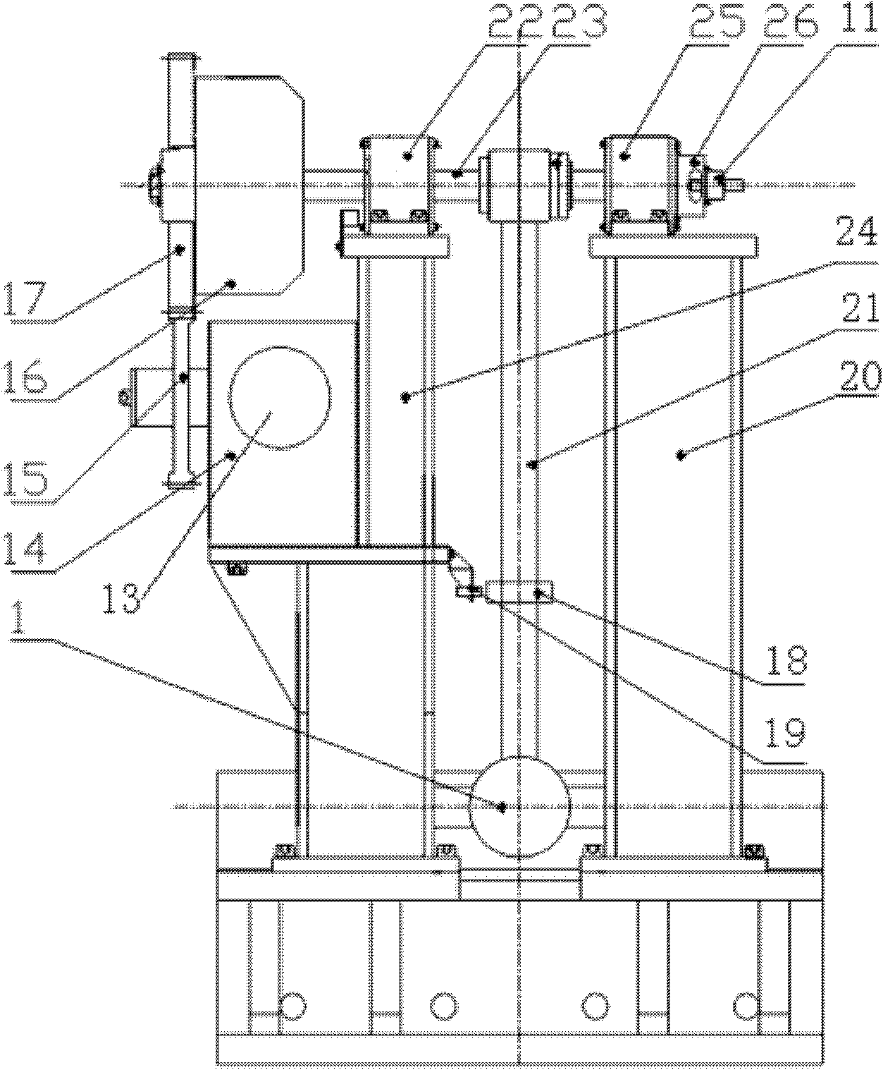
[0025] The present invention comprises base 2, two guide rails 4, 4 slide blocks 5 and 1 table top 8.

[0026] Six guide rail supports 9 are fixed on the base 2 with screws, and two guide rails 4 are fixedly installed on adjacent track supports 9 parallel to each other by screws. Two slide blocks 5 are worn on each guide rail 4 , and linear bearings are inlaid in the slide block 5 , and the slide block 5 can slide freely on the guide rail 4 . The upper surface of the slide block 5 and the lower surface of the table top 8 are fixedly installed by screws. The table top 8 is free to move in the axial direction of the guide rail 4 relative to the base 2 . The guide rail 4 can be a V-shaped guide rail, an optical shaft, a ball guide rail, etc., and the sliding linear bearing can be a V-shaped slide block, a self-lubricating linear bearing, a squa...


PUM


Abstract

The invention relates to a pendulum bob-type impact response spectrum testing bed which comprises a base, a guide rail, a sliding block and a bed face. A front waveform generator is fixed at one edge of the bed face, a back waveform generator is arranged on the base, the pendulum bob-type impact response spectrum testing bed further comprises a reducer fixedly connected with a left support, a motor connected with the reducer, a small gear connected with the reducer, a clutch and a pendulum bob rotation shaft, a big gear of the clutch is meshed with the small gear, the big gear of the clutch is fixedly connected with the pendulum bob rotation shaft, a friction hub of the clutch is fixedly connected with the pendulum bob rotation shaft, and the pendulum bob rotation shaft is supported by bearings fixed on the left support and a right support. The pendulum bob-type impact response spectrum testing bed further comprises an oscillating bar fixed on the pendulum bob rotation shaft and a pendulum bob fixed on the oscillating bar. The pendulum bob-type impact response spectrum testing bed achieves stable and rapid promotion of the pendulum bob and improves testing efficiency. The pendulum bob-type impact response spectrum testing bed enables the pendulum bob to slowly stop to achieve secondary impact resistance through friction plates and the friction hub. The pendulum bob-type impact response spectrum testing bed achieves bed face restoration, improves waveform quality and guarantees waveform consistency.

Description

technical field [0001] The invention relates to a pendulum type shock response spectrum test bench, in particular to a pendulum type shock response spectrum test bench which improves the lifting mode of the pendulum. Background technique [0002] The shock response spectrum test bench is mainly used to simulate the shock wave and shock energy suffered by the product in the real environment. It is mainly used in the fields of aerospace, aviation, electronics, automobiles, etc. It is a necessary impact test equipment in the development of satellites, launch vehicles, and electrical and electronic products. [0003] The shock response spectrum is the total result of the response of a series of single-degree-of-freedom linear systems with different natural frequencies when they are excited by the same shock. When the product is impacted, the maximum value of its shock response means that the product has the maximum stress at this point. The shock response spectrum is different...

Claims


Application Information

Patent Timeline
Patent Type & Authority Applications(China)
IPC IPC(8): G01M7/08
Inventor 田振强王冰张巧寿
Owner BEIJING AREOSTANARD NEW TECH
Why Eureka
Try Eureka