Liquid crystal display device and mould

A technology of a liquid crystal display device and a liquid crystal display module, which is applied in the direction of lighting devices, lighting auxiliary devices, lighting device components, etc., can solve the problems of complex assembly process, time-consuming and labor-intensive, etc., to reduce manufacturing costs, reduce component types, The effect of reducing the production cost of injection molding

Inactive Publication Date: 2012-12-26
SHENZHEN CHINA STAR OPTOELECTRONICS TECH CO LTD
View PDF3 Cites 9 Cited by
  • Summary
  • Abstract
  • Description
  • Claims
  • Application Information

AI Technical Summary

Problems solved by technology

The liquid crystal display module usually includes a front frame, a middle frame, a back plate, a liquid crystal display panel and a backlight module. The liquid crystal display panel is arranged between the front frame and the middle frame, and the backlight module is arranged between the middle frame and the backlight module. Between the boards, under normal circumstances, the assembly of the LCD device and the LCD module is completed in different factories. It is necessary to assemble the LCD module first, and then assemble the LCD device. Due to the complicated assembly process and the There are many parts in the device, and the parts need to be positioned and fixed with each other, which is time-consuming and labor-intensive, and needs to be improved

Method used


Image

  • Liquid crystal display device and mould
  • Liquid crystal display device and mould
  • Liquid crystal display device and mould

Examples


Embodiment Construction

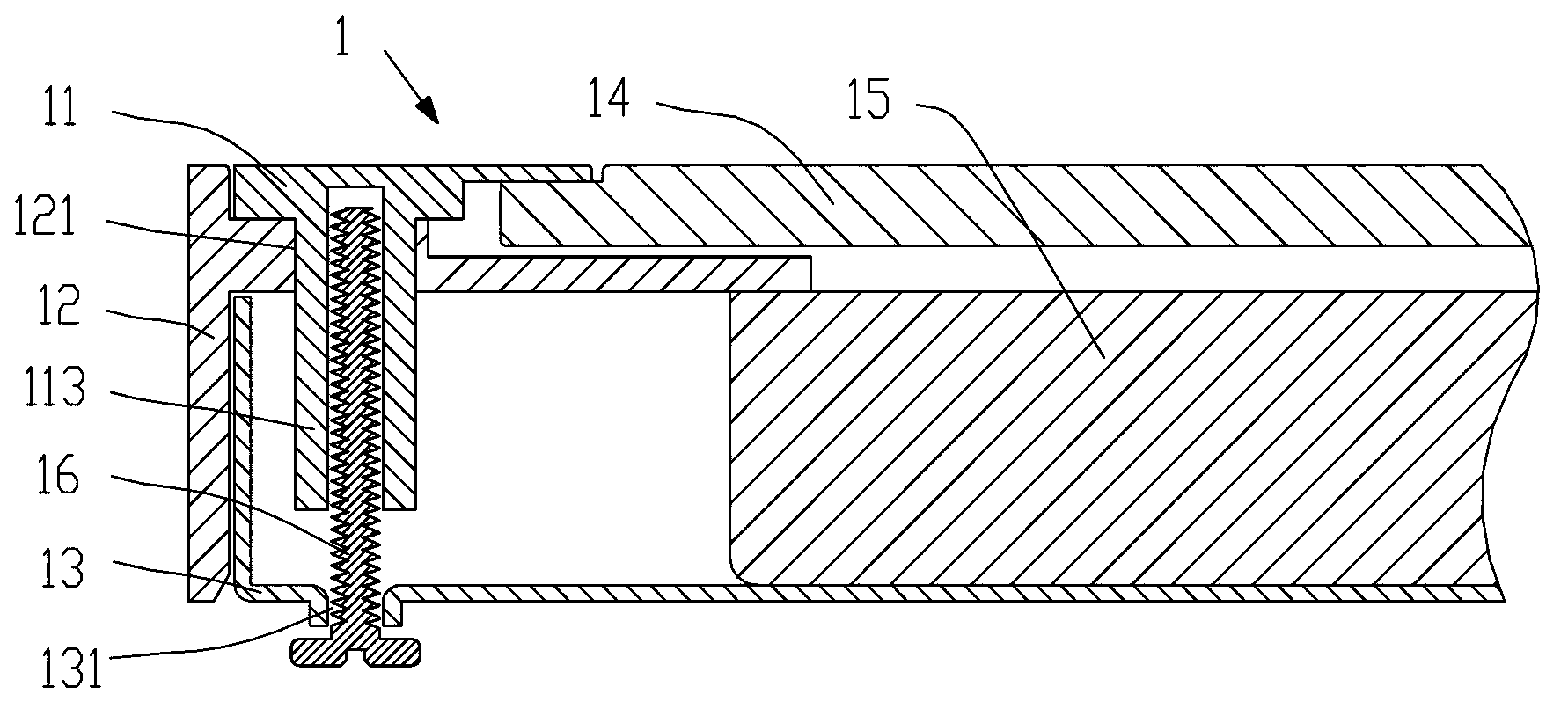
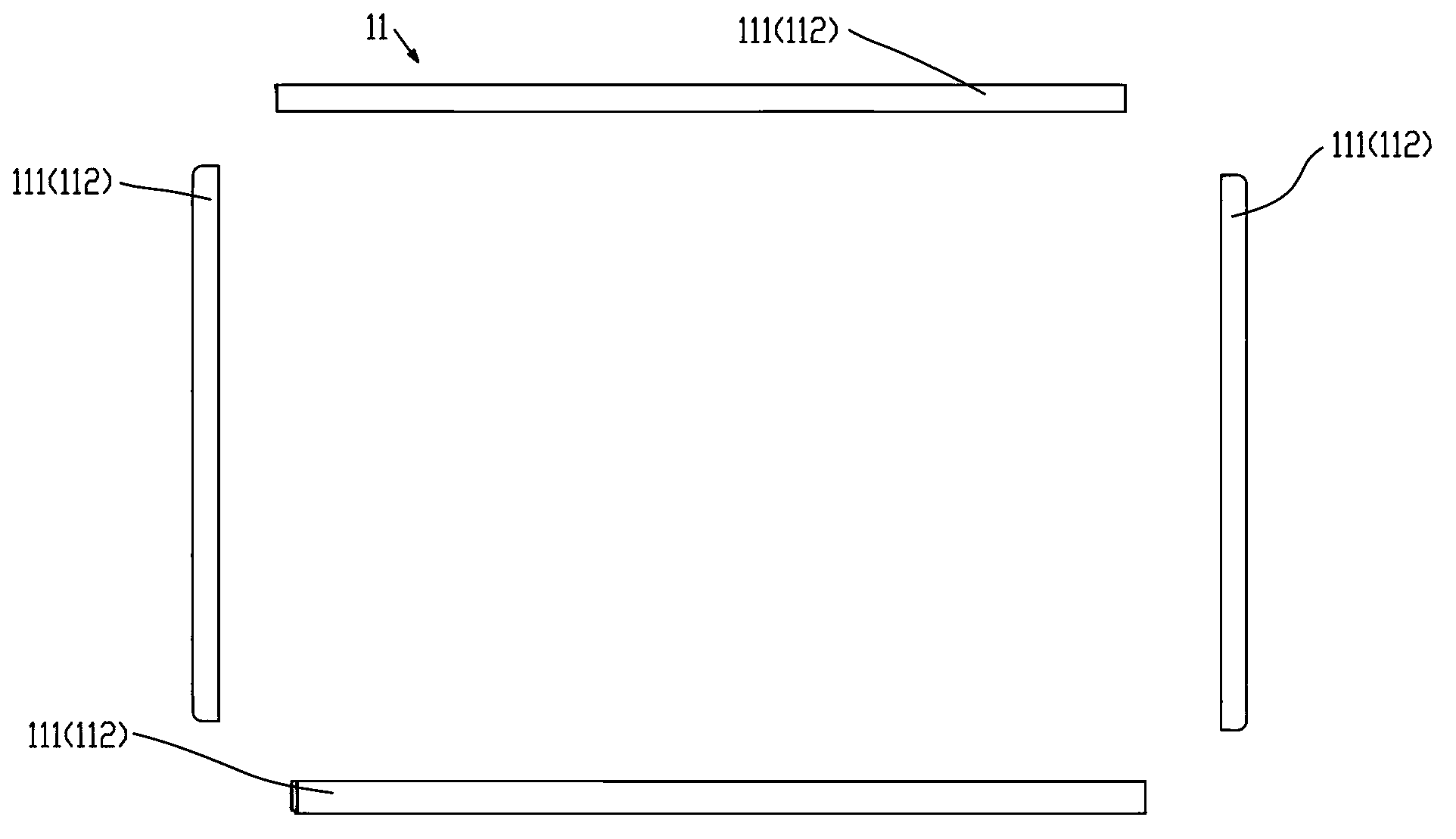
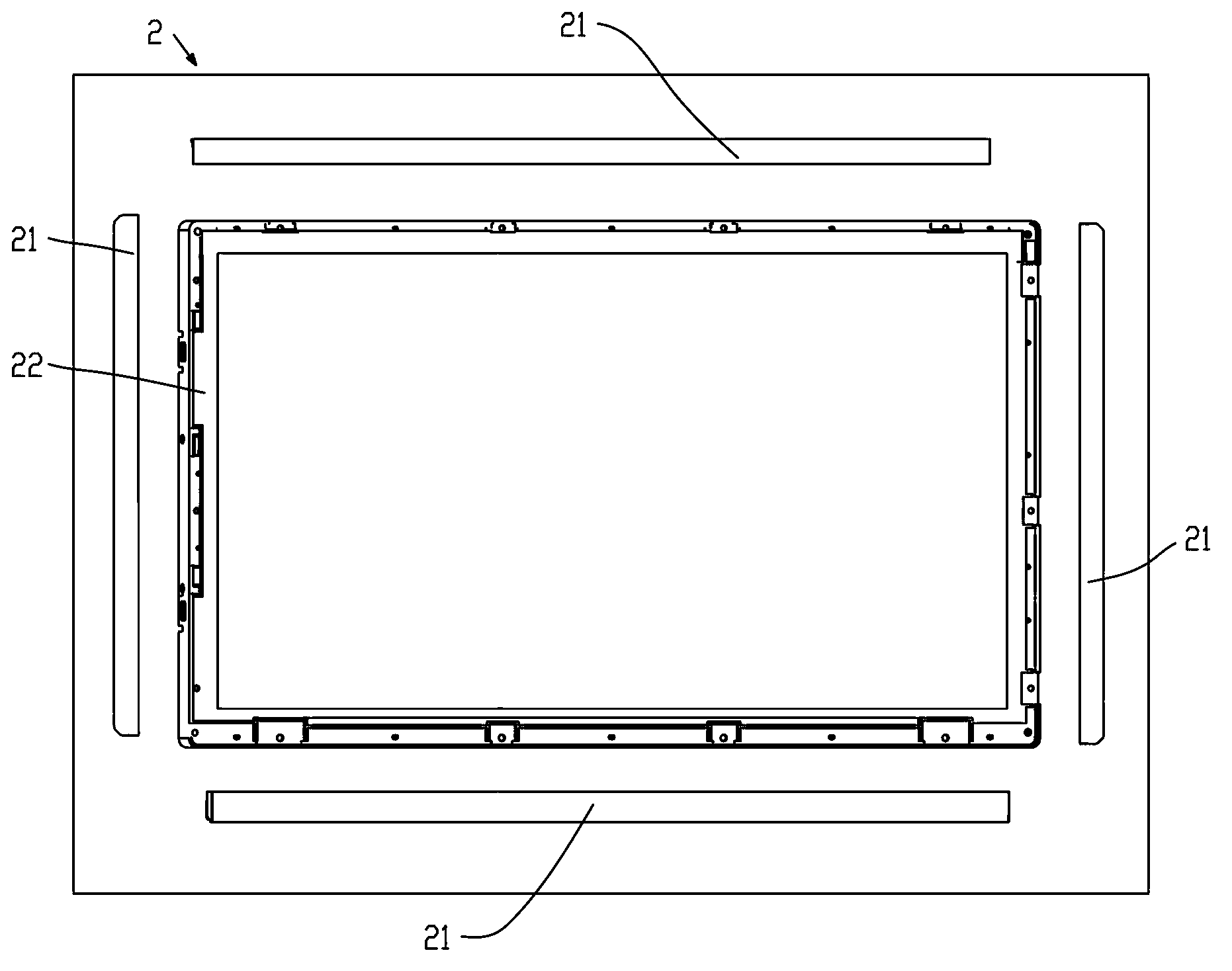
[0021] The invention discloses a liquid crystal display device. The liquid crystal display device can be a liquid crystal display for computers, a liquid crystal panel computer, or a liquid crystal TV. As an embodiment of the liquid crystal display device of the present invention, as figure 1 and figure 2 As shown, the liquid crystal display device includes a liquid crystal display module 1, and the liquid crystal display module 1 includes a front frame 11, a middle frame 12, a back plate 13, a liquid crystal display panel 14 and a backlight module 15, and the liquid crystal display panel 14 is set Between the front frame 11 and the middle frame 12, the backlight module 15 is arranged between the middle frame 12 and the back plate 13, the front frame 11 is also used as the front shell of the liquid crystal display device, and the back plate 13 is shared It is the back cover of the liquid crystal display device. The front frame 11 is a split structure and includes a plurality ...


PUM


Abstract

The invention belongs to the field of liquid crystal display and in particular relates to a liquid crystal display device and a mould. The liquid crystal display device comprises a liquid crystal display module, wherein the liquid crystal display module comprises a front frame, a middle frame, a rear panel, a liquid crystal display panel and a backlight module; the front frame is shared as a front shell of the liquid crystal display device; the rear panel is shared as a rear shell of the liquid crystal display device; the front frame has a split structure and comprises a plurality of component units; and the component units are bar-shaped or L-shaped. According to the liquid crystal display device, the front frame of the liquid crystal display module is shared as the front shell and the rear panel of the liquid crystal display module is shared as the rear shell; the two main parts of the front shell and the rear shell can be directly deleted by only moving some structures of the front shell onto the front frame and some structures of the rear shell onto the rear panel, so that the category of the parts is reduced and the manufacturing cost is lowered; and the assembling technology is simplified and the thinning design is realized.

Description

technical field [0001] The invention belongs to the field of liquid crystal display, and more specifically relates to a liquid crystal display device and a mold. Background technique [0002] Liquid crystal display technology has been widely used in various fields. LCD monitors for computers, LCD tablet computers and LCD TVs are the most common liquid crystal display devices. A complete liquid crystal display device usually includes a front case, a liquid crystal display module and a rear case. , the front shell and the rear shell are used to fix the liquid crystal display module, the front shell is also used for appearance decoration, and the rear shell is also used to fix the power supply board and the main board and so on. The liquid crystal display module usually includes a front frame, a middle frame, a back plate, a liquid crystal display panel and a backlight module. The liquid crystal display panel is arranged between the front frame and the middle frame. The backlig...

Claims


Application Information

Patent Timeline
Patent Type & Authority Applications(China)
IPC IPC(8): G02F1/13G02F1/13357F21V21/00H05K7/14B29C45/32
CPCB29C45/006B29L2031/3475G02F1/133308G02F1/13332G02F1/133325G02F1/133328
Inventor 张彦学萧宇均
Owner SHENZHEN CHINA STAR OPTOELECTRONICS TECH CO LTD
Why Eureka
Try Eureka