Shunt type air bath duct

A split-flow, air-bath technology, used in cooling/ventilation/heating transformation, photolithographic process exposure devices, microlithography exposure equipment, etc., can solve the problems of affecting flow, large piezoresistance, poor adjustment accuracy, etc. Energy consumption, solving mutual interference, reducing the effect of piezoresistance

Active Publication Date: 2012-12-26
SHANGHAI MICRO ELECTRONICS EQUIP (GRP) CO LTD
View PDF5 Cites 8 Cited by
  • Summary
  • Abstract
  • Description
  • Claims
  • Application Information

AI Technical Summary

Problems solved by technology

The air bath air duct adopting this flow adjustment method has a large system pressure resistance, and adjusting the valve on one branch will change the pressure resistance of the entire system, which will affect the flow of other branches, resulting in cumbersome flow adjustment process. And the adjustment accuracy is poor

Method used


Image

  • Shunt type air bath duct
  • Shunt type air bath duct
  • Shunt type air bath duct

Examples


Embodiment Construction

[0023] The idea, specific structure and technical effects of the present invention will be further described below in conjunction with the accompanying drawings, so as to fully understand the purpose, features and effects of the present invention.

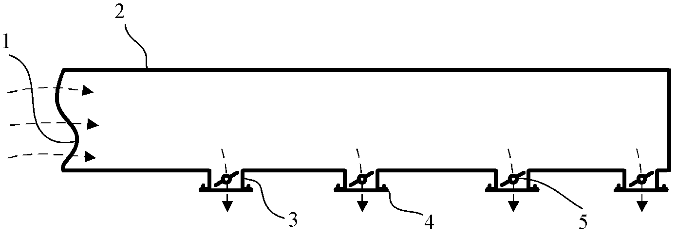
[0024] Figure 4 It is a schematic diagram of a split air bath air duct in a preferred embodiment of the present invention. Please refer to Figure 4 . The split-flow air bath air channel 40 provided in this embodiment can be installed in the overall frame of the photolithography machine to deliver the temperature-controlled air bath gas to various areas and components that require an air bath. Here, the split air bath duct 40 may include a body 400 and at least one split unit 410 . Here, the number of distribution units 410 may be multiple, and the height of the body 400 decreases sequentially with the distribution units 410 . However, the present invention does not impose any limitation thereto. In other embodiments, only on...


PUM


Abstract

The present invention discloses a shunt type air bath duct, which comprises a body and at least a shunt unit. The body is provided with at least one branch air outlet. The shunt unit and the branch air outlet are correspondingly arranged one-to-one. The height of the body is sequentially reduced along with the shunt unit. The shunt unit comprises a regulation member and a shunt piece, wherein the regulation member can be movably arranged on the body and connected with the shunt piece, and the shunt piece is parallel to the body. With the shunt type air bath duct of the present invention, flows of various branches can be regulated, the problem of mutual interference of branch flow regulation is solved, piezoresistance of the air bath system is reduced, and energy consumption is saved.

Description

technical field [0001] The invention relates to an air bath air duct, in particular to a split-flow air bath air duct. Background technique [0002] The lithography machine is a high-precision equipment, and the internal environment and the temperature of the components have a great influence on the lithography accuracy. There are many heat sources inside the lithography machine. The heat generated by these heat sources will affect the stability of the components and space temperature in the system and must be controlled. The air bath is one of the main means of temperature control of the lithography machine. By applying a constant temperature air bath to the workpiece table, mask table, silicon wafer transmission and other areas and components, the stability and uniformity of the space and component temperature can be achieved. The design of the air bath duct is to deliver the temperature-controlled air bath gas to various areas and components that require an air bath. ...

Claims


Application Information

Patent Timeline
Patent Type & Authority Applications(China)
IPC IPC(8): G03F7/20H05K7/20
Inventor 张洪博聂宏飞
Owner SHANGHAI MICRO ELECTRONICS EQUIP (GRP) CO LTD
Why Eureka
Try Eureka