
Intelligent monitoring method for power cabinet door state

A technology of intelligent monitoring and cabinet doors, applied in the direction of electrical program control, comprehensive factory control, comprehensive factory control, etc., can solve the problems of unable to collect door opening and closing operators, the number and location of power cabinets are dispersed, and the monitoring effect cannot be obtained, etc., to achieve The construction layout is simple and convenient, the monitoring function is perfect, and the installation is convenient

Active Publication Date: 2012-12-26
NORTH CHINA ELECTRIC POWER UNIV (BAODING)
View PDF5 Cites 12 Cited by
  • Summary
  • Abstract
  • Description
  • Claims
  • Application Information

AI Technical Summary

Problems solved by technology

However, because the existing door lock monitoring devices have relatively simple functions, do not have the function of downlink control, and cannot collect the information of the operator who opens and closes the door, so the monitoring of the power cabinet is mainly realized through a limited number of video monitoring equipment. This requires electric power staff to be on duty 24 hours a day, check the monitoring, and find the cause of the fault by consulting video records when a power fault occurs
Due to the relatively high cost of video equipment and limited field of vision, and the large number of power cabinets and scattered locations, these video equipment cannot obtain good monitoring results

Method used


Image

  • Intelligent monitoring method for power cabinet door state
  • Intelligent monitoring method for power cabinet door state
  • Intelligent monitoring method for power cabinet door state

Examples


Embodiment Construction

[0024] The present invention adopts a kind of warning alarm system in the cabinet door state monitoring and maintenance operation process based on 433MHz frequency band radio frequency module CC1110, compared with the existing wireless state monitoring device based on the ZigBee radio frequency module of 2.4GHz frequency band, the system signal The penetration ability is better. Under the premise of the same transmission power, the distance of wireless transmission control is longer and the function is more perfect.

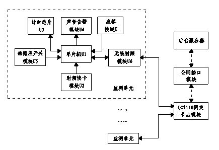
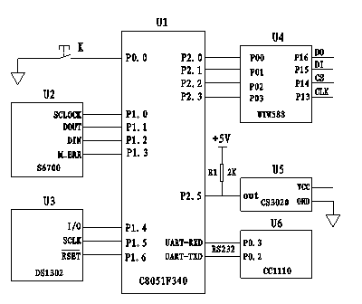
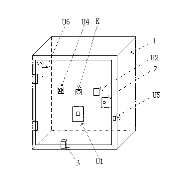
[0025] see figure 1 , the monitoring device used in the present invention is made up of background server and the cabinet door state monitoring unit that is installed on each power cabinet, and each power cabinet is all equipped with a set of wireless monitoring unit based on 433MHz frequency band radio frequency module CC1110, and each monitoring unit includes: Magnetic induction switch module U5, timing chip U3, sound alarm module U4, answer button K, radio fre...


PUM


Abstract

The invention discloses an intelligent monitoring method for the power cabinet door state, which comprises the following steps of: a cabinet door status monitoring unit which takes a single chip microcomputer as a core control component and comprises a magnetic induction switch module, a timing chip, a radio frequency card-reading module and a wireless radio frequency module is installed in each power cabinet; the single chip microcomputer detects the switching status of the cabinet door of the power cabinet in real time by the magnetic induction switch module; when a door opening signal is received, the timing chip is immediately started; radio frequency card information carried by operating personnel is read by the radio frequency card-reading module; and the single chip microcomputer sends and stores the cabinet door number and the door opening and closing time of the opened power cabinet as well as the information of the operation personnel to a background server via a wireless radio frequency module. Compared with the traditional door lock monitoring method for the power cabinet door, the intelligent monitoring method for the power cabinet door state, which is disclosed by the invention, has the advantages of convenient equipment installation, long communication transmission distance and perfect monitoring function, and the working efficiency of the power cabinet maintenance and the management level of a power company can be greatly improved.

Description

technical field [0001] The invention relates to a method for monitoring the state of a cabinet door of an electric cabinet in an unattended power distribution substation, and belongs to the technical field of switch devices. Background technique [0002] At present, the power cabinets of distribution substations are equipped with fixed door locks. When electric power workers inspect and maintain power cabinets, they need to obtain the keys of the door locks and operate according to existing procedures and specifications. However, if the number of power cabinets is large, the workload is large, and the operation is cumbersome, and the staff is not familiar with the operation process and specifications, and does not pay attention to them, then it is easy to misuse or irregularly operate the power cabinets, directly Threat to the safe and reliable operation of the power system. A typical example is that the power cabinet is opened and forgot to close the door or the door has b...

Claims


Application Information

Patent Timeline
Patent Type & Authority Applications(China)
IPC IPC(8): G05B19/418
CPCY02P90/02
Inventor 陈智雄项洪印
Owner NORTH CHINA ELECTRIC POWER UNIV (BAODING)
Learn More