Eureka AIR delivers breakthrough ideas for toughest innovation challenges, trusted by R&D personnel around the world.

Rapid high-precision photovoltaic array maximum power point tracking control method

A technology of maximum power point and photovoltaic array, which is applied in the field of solar photovoltaic power generation, can solve problems such as energy waste and system instability, and achieve the effects of economical reliability, guaranteed continuity, and improved utilization

Inactive Publication Date: 2012-12-26
SOUTHEAST UNIV
View PDF3 Cites 11 Cited by
  • Summary
  • Abstract
  • Description
  • Claims
  • Application Information

AI Technical Summary

Problems solved by technology

[0004] Technical problem: Aiming at the shortcomings of the traditional maximum power point tracking method, the present invention proposes a fast and high-precision maximum power point tracking control method for photovoltaic arrays, which organically combines the short-circuit current method and the conductance incremental method, and takes into account the traditional short-circuit current In the method, the detection of short-circuit current will cause the system to suspend operation, resulting in system instability and energy waste. The present invention adopts the method of online detection of short-circuit current, which eliminates the impact on system operation and improves stability and efficiency.

Method used


Image

  • Rapid high-precision photovoltaic array maximum power point tracking control method
  • Rapid high-precision photovoltaic array maximum power point tracking control method
  • Rapid high-precision photovoltaic array maximum power point tracking control method

Examples


Embodiment Construction

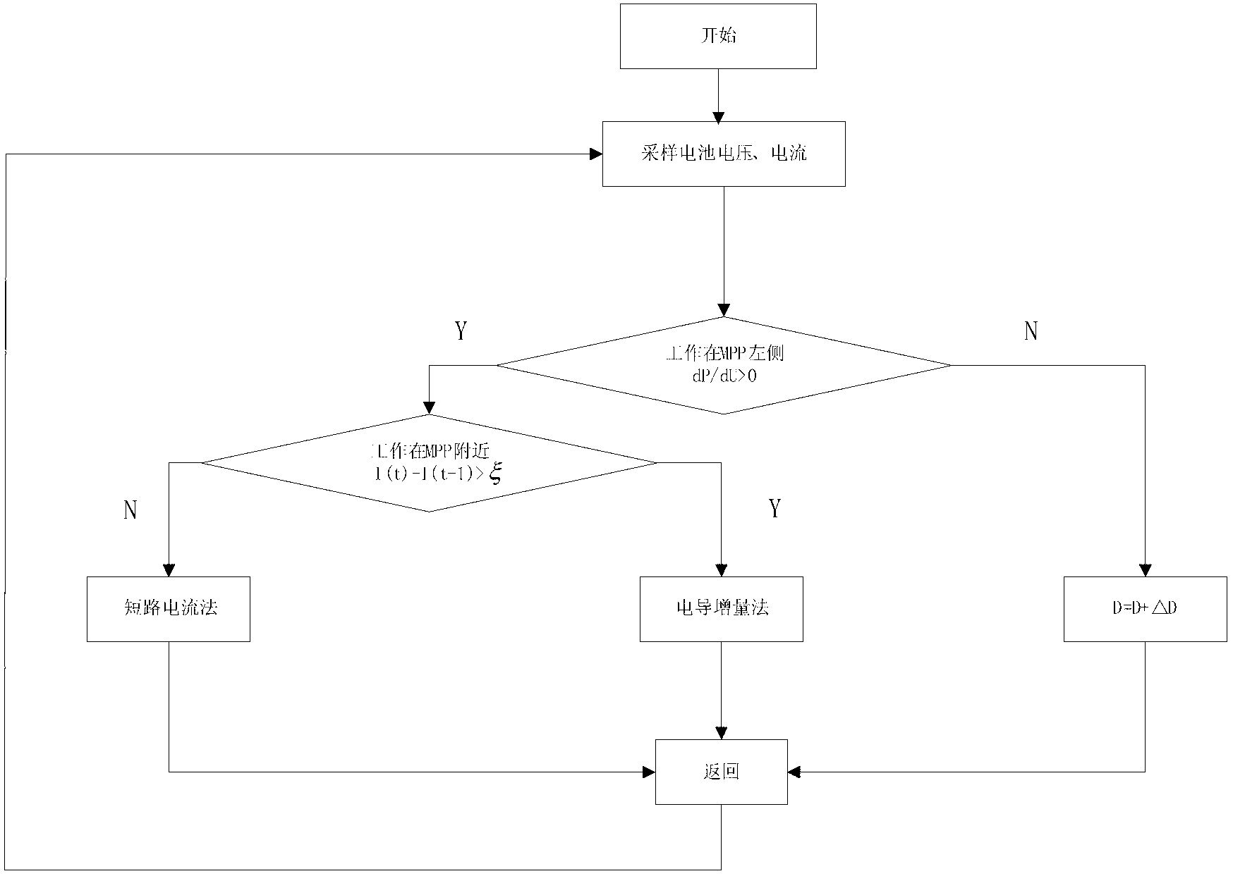
[0020] 1) Define a certain working time of the system as t, sample the output voltage and output current of the photovoltaic cell at time t, and calculate the output power;

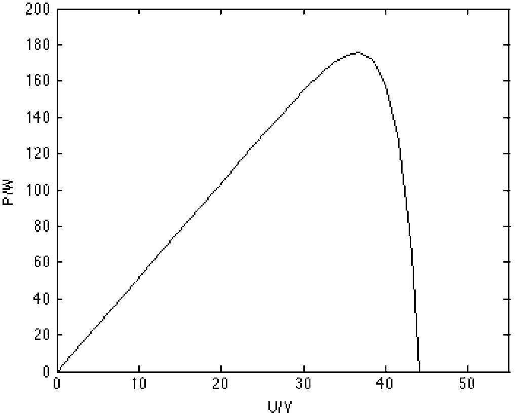
[0021] 2) Compare the power and voltage at time t with the power and voltage at time t-1, and judge whether the system is working on the left side of the maximum power point according to the positive or negative of dP / dU, where dP refers to the adjacent sampling time dU refers to the voltage difference at adjacent sampling moments, and the left side of the maximum power point refers to: the voltage at the system operating point is less than the voltage at the maximum power point;

[0022] 3) If the system operating point is not on the left side of the maximum power point, adjust the duty cycle so that the system works on the left side of the maximum power point;

[0023] 4) Make sure that the system works on the left side of the maximum power point, then use the formula I(t)=dP(t) / dU(t) to get I(t) and I(...


PUM


Abstract

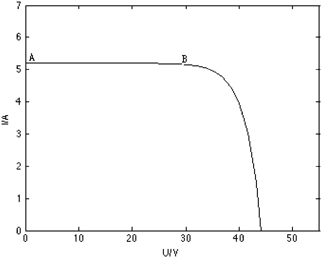
The invention provides a rapid high-precision photovoltaic array maximum power point tracking control method which combines a short circuit current method and a conductance incremental method and achieves complementary advantages of the two methods. Output voltage and output current of a photovoltaic cell are adopted to judge if a system is in motion of the left side of the maximum power point, if not, the system is enabled to be in motion of the left side of the maximum power point by means of the adjustment of a duty ratio; values of dP / dU are obtained, a value approximately equal to a short circuit current value I s is taken, the corresponding maximum power point current I meter ( I meter is equal to 0.92 I s) is worked out and applied to the control of the short circuit current method; the current is sampled and output, difference values of the sampling current at adjacent time are compared, when the difference value is greater than a setting range, that is, the system is in motion near the maximum power point, at the moment the system is switched to the conductance incremental method to run until the maximum power point is searched. The rapid high-precision photovoltaic array maximum power point tracking control method is quick in dynamic response and high in tracking precision, and at the same time, greatly reduces interference caused by a traditional short circuit current method to the motion of the system, and improves output efficiency of a photovoltaic cell.

Description

technical field [0001] The invention relates to a photovoltaic array MPPT (maximum power point tracking) control method, which belongs to the technical field of solar photovoltaic power generation. Background technique [0002] In today's society, the increasing shortage of non-renewable energy and the increasing environmental pollution have made the use of renewable energy such as solar energy attract the attention of the government and all walks of life, and photovoltaic power generation technology has also developed rapidly. Photovoltaic array maximum power point tracking technology is one of the main technologies involved in photovoltaic power generation. [0003] At present, the commonly used maximum power point tracking control methods include: constant voltage method, short-circuit current method, disturbance observation method, conductance increment method, fuzzy control method, etc., and there are some improved methods based on the above methods. The constant volta...

Claims


Application Information

Patent Timeline
IPC IPC(8): G05F1/67
CPCY02E10/58Y02E10/56
Inventor 林明耀吴威林克曼骆皓
Owner SOUTHEAST UNIV
Why Eureka
Eureka Blog
Learn More