Online calibrating method and device for rotor time constant of asynchronous motor and control system

A rotor time constant, asynchronous motor technology, applied in control systems, vector control systems, motor generator control and other directions, can solve problems such as high hardware requirements, changing parameter setting values, and inability to give full play to the control performance of asynchronous motors. Simple, low hardware requirements

Active Publication Date: 2012-12-26
CRRC YONGJI ELECTRIC CO LTD
View PDF3 Cites 17 Cited by
  • Summary
  • Abstract
  • Description
  • Claims
  • Application Information

AI Technical Summary

Problems solved by technology

[0005] In the prior art, the parameter setting value in the control system of the asynchronous motor mainly adopts the hot state value or the cold state value of the asynchronous motor, but using the hot state value or the cold state value of the parameter as the parameter setting value cannot set the parameter according to the state of the asynchronous motor Therefore, the control performance of the asynchronous motor cannot be fully utilized
[0006] In the prior art, there are also control methods that add parameter online identification technology, or use a control strategy that is highly robust to parameters, and improve the performance of the control system by real-time correction of motor parameters. Control strategy with strong parameter robustness The control algorithm is complex, the requirements for hardware are high, and the development is difficult

Method used


Image

  • Online calibrating method and device for rotor time constant of asynchronous motor and control system
  • Online calibrating method and device for rotor time constant of asynchronous motor and control system
  • Online calibrating method and device for rotor time constant of asynchronous motor and control system

Examples


Embodiment Construction

[0045] In order to make the purpose, technical solutions and advantages of the embodiments of the present invention clearer, the technical solutions in the embodiments of the present invention will be clearly and completely described below in conjunction with the drawings in the embodiments of the present invention. Obviously, the described embodiments It is a part of embodiments of the present invention, but not all embodiments. Based on the embodiments of the present invention, all other embodiments obtained by persons of ordinary skill in the art without creative efforts fall within the protection scope of the present invention.

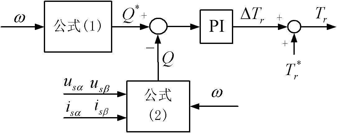
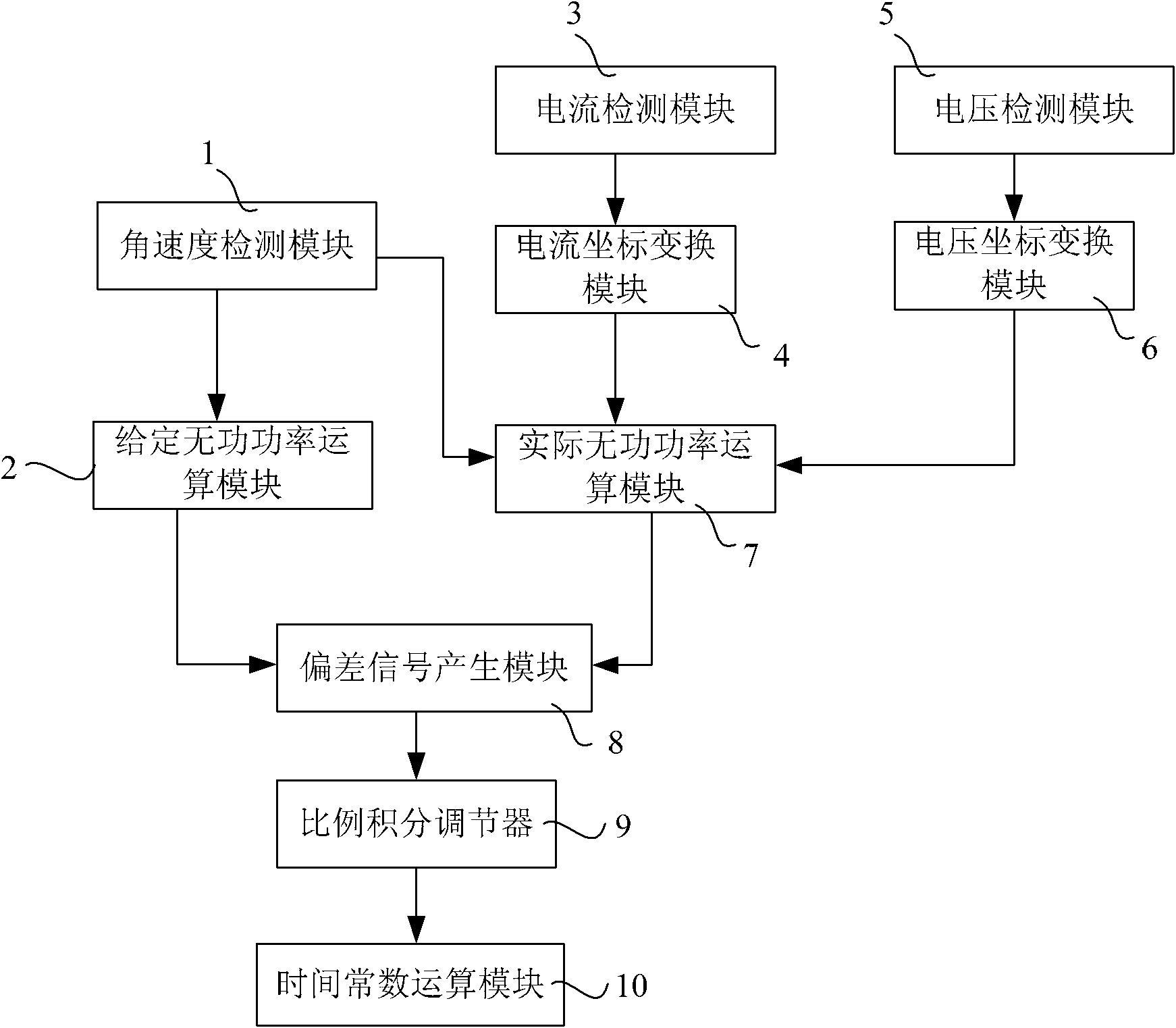
[0046] figure 1 It is a flow chart of the online correction method for the rotor time constant of an asynchronous motor provided by the embodiment of the present invention, figure 2 The principle diagram of the online correction method for the rotor time constant of the asynchronous motor provided by the embodiment of the present invention, as s...


PUM


Abstract

The invention discloses an online calibrating method and device for a rotor time constant of an asynchronous motor, and an asynchronous motor driving control system. The calibrating method comprises the following steps: measuring the angular velocity of a rotor, the current of a stator and the voltage of the stator; calculating a given reactive power and an actual reactive power of a motor based on a formula; making a comparison between the given reactive power and the calculated actual reactive power served as a feedback reactive power, so as to generate a deviation signal; adjusting the deviation signal through a proportional-integral controller in order to output an adjusting value of a rotor time constant; calibrating the setting value of the rotor time constant based on the adjusting value, thus meeting the setting value of the rotor time constant in line with the actual value. The calibrating method is simple, and is low in requirement on hardware.

Description

technical field [0001] The invention relates to motor control technology, in particular to an on-line correction method and device for the rotor time constant of an asynchronous motor, and an asynchronous motor drive control system. Background technique [0002] Asynchronous motors are widely used in industry and agriculture due to their strong and durable, reliable operation and low maintenance. However, the performance of asynchronous motors depends heavily on motor parameters, including parameters such as stator resistance, stator leakage reactance, rotor resistance, rotor leakage reactance, excitation impedance, and rotor time constant, especially the rotor time constant. The fluctuation of the rotor time constant will cause the output torque of the motor And motor voltage fluctuations affect the efficiency of the motor. [0003] In the control system of asynchronous motor, it is necessary to make the setting value of the motor consistent with the actual value as much a...

Claims


Application Information

Patent Timeline
Patent Type & Authority Applications(China)
IPC IPC(8): H02P25/02H02P21/14H02P21/16
Inventor 宋春龙陈振锋曾礼
Owner CRRC YONGJI ELECTRIC CO LTD
Why Eureka
Try Eureka