Phase-locked loop, microwave modem and phase jump suppressing method
A technology of phase-locked loop and phase detector, which is applied in the direction of automatic power control and electrical components, can solve the problems of high bit error rate and high performance risk of modem, and achieve the effect of reducing bit error rate and risk
- Summary
- Abstract
- Description
- Claims
- Application Information
AI Technical Summary
Problems solved by technology
Method used
Image
Examples
Embodiment 1
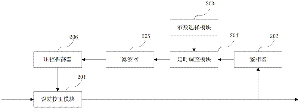
[0037] See figure 2 , which shows a device structure diagram of a phase-locked loop provided in the first embodiment. The phase locked loop can be applied to suppress the phase jump of the ODU signal in the microwave modem. The phase-locked loop may specifically include: an error correction module 201, a phase detector 202, a parameter selection module 203, a delay adjustment module 204, a filter 205 and a control oscillator 206;
[0038] An error correction module 201, configured to correct the input data according to the correction signal to obtain corrected data;
[0039] A phase detector 202, configured to perform error phase detection on the data corrected by the error correction module 201 according to the current modulation mode, to obtain a phase detector error;
[0040] A parameter selection module 203, configured to select a corresponding loop bandwidth parameter according to the current modulation mode;
[0041] The delay adjustment module 204 is used to delay t...
Embodiment 2
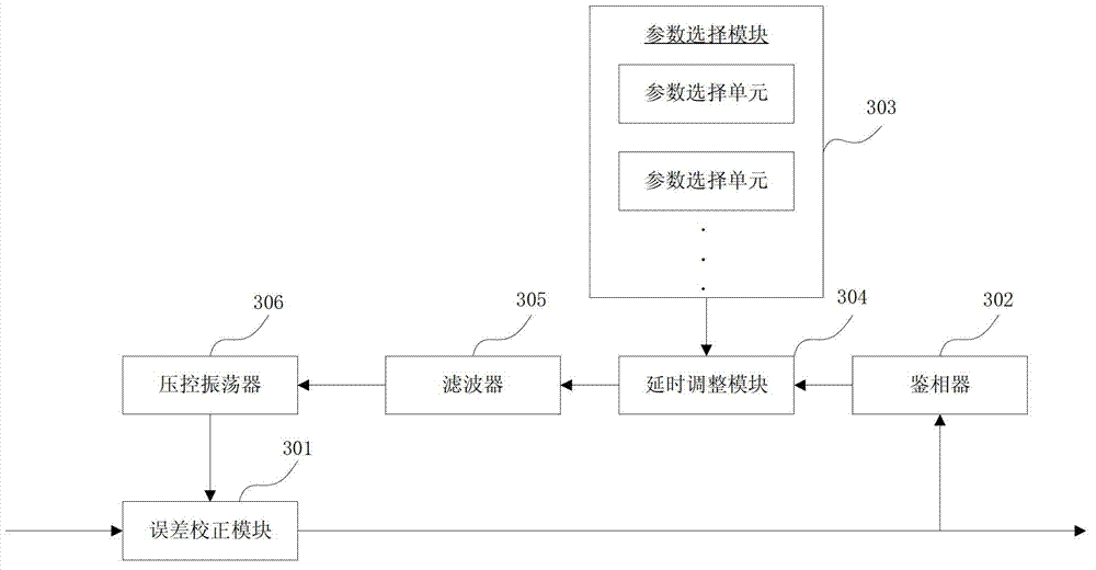
[0046] See image 3 , which shows a device structure diagram of a phase-locked loop provided in the second embodiment. The phase locked loop can be applied to suppress the phase jump of the ODU signal in the microwave modem. The phase-locked loop may specifically include:
[0047] Error correction module 301, phase detector 302, parameter selection module 303, delay adjustment module 304, filter 305 and control oscillator 306;
[0048] An error correction module 301, configured to correct the input data according to the correction signal to obtain corrected data;
[0049] Specifically, the error correction module 301 corrects the service data input to the microwave modem according to the correction signal generated by the error correction module, and outputs the corrected service data.
[0050] A phase detector 302, configured to perform error phase detection on the data corrected by the error correction module 301 according to the current modulation mode, to obtain a phase...
Embodiment 3
[0079] See Figure 7 , which shows a method flow chart of a phase jump suppression method provided in the third embodiment, and the phase jump suppression method can be applied to suppress phase jump through a phase-locked loop in a microwave modem. The phase jump suppression method may include:
[0080] Step 701, correcting the input data according to the correction signal to obtain the corrected data;
[0081] The phase-locked loop in the microwave modem first corrects the service data input into the microwave modem according to the initial correction signal, and outputs the corrected data.
[0082] Step 702, performing error phase detection on the corrected data according to the current modulation mode to obtain phase detector error;
[0083] The phase-locked loop in the microwave modem can determine the ideal data model according to the current modulation mode, and perform error phase detection on the corrected service data according to the determined data model to obtai...
PUM
 Abstract
Description
Claims
Application Information
 - R&D
- Intellectual Property
- Life Sciences
- Materials
- Tech Scout
- Unparalleled Data Quality
- Higher Quality Content
- 60% Fewer Hallucinations
Browse by: Latest US Patents, China's latest patents, Technical Efficacy Thesaurus, Application Domain, Technology Topic, Popular Technical Reports.
© 2025 PatSnap. All rights reserved.Legal|Privacy policy|Modern Slavery Act Transparency Statement|Sitemap|About US| Contact US: help@patsnap.com


